ARMY TM 9-6115-642-24
AIR FORCE TO 35C2-3-455-12
MARINE CORPS TM 09247A/09248A-24/2
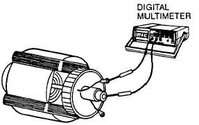
h. Connect multimeter leads between F1+ and rotor shaft and between F2-and rotorshaft inturn (FIGURE 4-21).
Multimeter should not register.
FIGURE 4-21. Testing Rotor for Grounds
i.
If multimeter registers, rotor is grounded and must be replaced.
j.
Connect F1+ and F2- leads to rotating rectifier assemblies. Tighten nuts to 24 in-lbs (2.7 Nm).
k.
Install end bell cover on generator, paragraph 4-11.4, step n (MEP-803A) or paragraph 4-12.5, step g
(MEP-813A).
l.
Connect negative battery cable and close access doors.
4-10.7 Testing Generator Stator. Using resistance bridge and multimeter, set for ohms, test the stator for grounds,
opens, and shorts in the windings as follows:
a.
b.
c.
d.
e.
f.
g.
h.
i .
j.
k.
l.
m.
n.
Shut down generator set. Allow generator to cool to ambient temperature.
Open left side engine access door and disconnect negative battery cable.
Remove control box top panel, paragraph 2–1 6.1.
Tag and disconnect twelve main generator coil leads from TB3 in output box.
Tag and disconnect Q1 and Q2 leads from terminals 7 and 8 of AC voltage regulator.
Open storage box and output terminal board access doors.
Connect resistance bridge between coil leads (FIGURE 4-22). All readings should be as shown for generator
stator leads in TABLE 4-1.
Connect resistance bridge between leads Q1 and Q2. Reading should be as shown in TABLE 4-1.
NOTE
Before replacing stator assembly, check leads for broken wires or insulation. Repair or
replace, as necessary.
If resistance is low, there are shorted windings. If resistance is high, stator winding is open. In either case, stator
must be replaced.
Connect multimeter between generator housing and generator set ground. Multimeter should register.
Connect multimeter between each coil lead and generator housing, in turn. Multimeter should not register.
If multimeter registers on any reading, stator windings are grounded and stator assembly must be replaced.
Connect Q1 and Q2 leads to terminals 7 and 8 of AC voltage regulator and remove tags.
Connect main generator coil leads to TB3 and remove tags.
4-23