ARMY TM 9-6115-642-24
AIR FORCE TO 35C2-3-455-12
MARINE CORPS TM 09247A/09248A-24/2
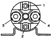
FIGURE 2-17. Pre-Heat Relay Terminals
2-63.4
lnstallation.
a.
Install preheat relay (10, FIGURE 2-16) in output box with bolts (7), Iockwashers
b. Connect electrical leads and remove tags.
c.
Install control box top panel, paragraph 2-16.4.
d. Connect negative battery cable and close access door.
(8), and washers (9).
2-64.1
a.
b.
c.
d.
e.
f.
2-64.2
a.
b.
c.
d.
e.
f.
2-64.3
a.
b.
c.
d.
e.
lnspection.
Shut down generator set.
Open left side engine access door and disconnect negative battery cable.
Remove control box top panel, paragraph 2-16.1.
Inspect voltage reconnection switch (16, FIGURE 2-16) for cracks, missing parts, and loose hardware.
Install control box top panel, paragraph 2-16.4.
Connect negative battery cable and close access door.
Removal.
Shut down generator set.
Open left engine access door and disconnect negative battery cable.
Remove control box assembly, paragraph 2-21.2.
Tag and disconnect electrical leads to voltage reconnection switch (16, FIGURE 2-16).
When removing the voltage reconnection switch, use extreme care not to drop
the attaching hardware down on the generator unit. Serious damage to equip-
ment could occur.
Remove screws (11) and (14), washers (12), nuts (13) and (15), and voltage reconnection switch (16) from
output box assembly.
Remove screws (17) and mounting bracket (18) from output box assembly.
Testing.
Remove voltage reconnection switch, paragraph 2-64.2.
Set multimeter for ohms and check voltage reconnection switch for continuity. Refer to Electrical Schematic
FO-1 (S-8 Circuit Schedule) to determine switch circuits made to corresponding switch positions.
Check continuity of switch circuits in all three switch positions.
If open circuit is indicated in any switch position, voltage reconnection switch is defective and must be replaced.
If replacement is not required, install voltage reconnection switch, paragraph 2-64.4.
2-91
2-64 VOLTAGE RECONNECTION SWITCH.