ARMY TM 9-6115-641-24
AIR FORCE TO 35C2-3-456-12
4-1-3. Testing - Continued.
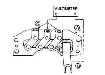
Figure 4-4. Rectifier Bridge Test
d.
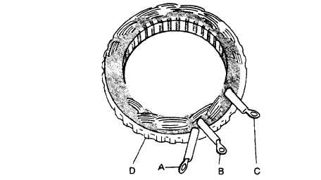
Set multimeter for ohms and check stator (Figure 4-5) for open circuits between point D (laminations) and each
terminal A, B, and C. If continuity is noted between laminations and any terminal, stator is defective and must
be replaced.
Figure 4-5. Stator Winding Test
NOTE
Place test leads on edges of slip rings to avoid creating arcs on brush contact surfaces.
e.
Set multimeter for ohms and check rotor assembly (Figure 4-6) for 40.5 – 43.8 ohms indication between slip
rings. Also check that open circuits are indicated between rotor body and each slip ring. Replace entire rotor
assembly if indications are other than stated.
4-3


