ARMY TM 9-6115-641-24
AIR FORCE TO 35C2-3-456-12
4-1-2. Inspection.
a.
Inspect brushes for cracks, grooves on sides, being oil soaked, and that they are at least 3/16 in. (4.76 mm)
long.
b.
Inspect rear housing for cracked or broken casting, stripped threads, and severe wear of rear bearing bore.
c.
Inspect fan for cracked or broken fins and for worn mounting hole.
d. Inspect front housing for cracked or broken casting, stripped threads, and bore in mounting foot for elongation.
e.
Inspect other components for damage such as broken terminals or insulation, discoloration, stripped threads,
and other obvious damage.
f.
Replace damaged components as necessary.
4-1-3. Testing.
a.
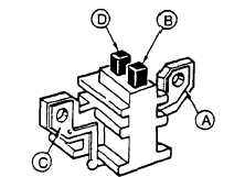
Set multimeter for ohms and check brush assembly (Figure 4-2) for continuity between mount A and brush
B, and mount C and brush D. Check for open circuits between mount A and mount C, mount A and brush D,
mount C and brush B, and brush B and brush D. Replace brush assembly if indications are other than stated.
Figure 4-2. Brush Test
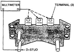
b. Set multimeter for ohms and check diode-trio assembly (Figure 4-3) by noting multimeter indications between
D+ stud and each of stator terminals. Reverse multimeter leads, repeat checks and note indications. If readings
are the same in both directions for any diode, replace entire diode-trio assembly. A good diode will show a high
indication in one direction and a low indication in the other.
Figure 4-3. Diode-Trio Test
c.
Set multimeter for ohms and check rectifier bridge assembly (Figure 4-4) by noting multimeter indications be-
tween point A and each point C, and between point B and each point C. Reverse leads, repeat checks and note
indications. If readings are the same in both directions for any diode, replace entire rectifier bridge assembly.
A good diode will have a high indication in one direction and a low indication in the other.
4-2