ARMY TM 9-6115-641-10
AIR FORCE TO 35C2-3-456-11
The batteries are charged by the battery charging
alternator that is belt driven by the engine. Generator set
control system power is also supplied by the battery
charging alternator. The BATTERY CHARGE ammeter
indicates the charge/discharge rate of the batteries, from
-10 AMPS to +20 AMPS, in 5 AMPS increments. Normal
operating indication depends on the state of charge in the
batteries. A low charge, such as exists immediately after
engine starting, will cause a high reading (needle moves
toward CHARGE area). When the charge in the batteries
has bean restored, the indicator moves near zero, 0.
1-12
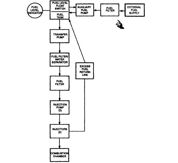
The Fuel System (FIGURE 1-4), consists of piping, fuel
tank, fuel filter, electrically driven transfer pump, fuel
filter/water separator, two injection pumps and two
injectors, one for each cylinder. Fuel is drawn from the fuel
tank by the transfer pump when the MASTER SWITCH is
in the PRIME & RUN position. After reaching the transfer
pump, fuel passes through a fuel filter/water separator
where water and small impurities are removed. The fuel
then goes to the injection pumps where it is pressurized
and pushed into the injectors. Through the injectors fuel
enters the diesel engine combustion chamber, where it is
mixed with air and ignited. The fuel that is not used is
returned to the fuel tank via an excess fuel return line.
The Auxiliary Fuel System consists of an external fuel
supply, fuel filter piping, a 24 VDC auxiliary fuel pump and
a fuel Ievel float switch. When the MASTER SWITCH is
set on PRIME& RUN AUX FUEL it actuates the auxiliary
fuel pump and transfers fuel from the external
Figure 1-4. Fuel System
1-12 Change 1