ARMY TM 9-6115-641-10
AIR FORCE TO 35C2-3-456-11
SECTION Ill . TECHNICAL PRINCIPLES OF OPERATION
1-10
This section contains functional descriptions of the
generator set and explains how the controls and indicators
1-11
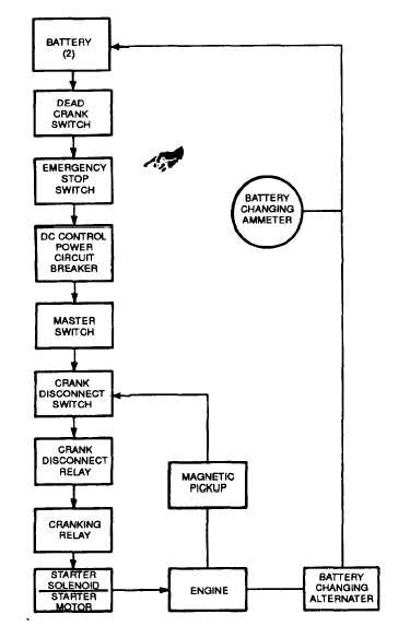
The Engine Starting System (FIGURE 1-3), consists of
two 12-volt batteries connected in series, a starter, a 24
volt battery charging alternator, a magnetic pickup (for
sensing engine speed) and the related switches and
relays required for control of the starting system. For
engine cranking, battery power is supplied to the starter
motor through the starter solenoid which in turn is
controlled by the cranking relay. The starter then engages
the engine flywheel causing the engine to turn over. For
engine starting, the DEAD CRANK switch must be in the
NORMAL position, the DC Control power circuit breaker
must be pushed in, the EMERGENCY STOP SWITCH
must be in the OUT position, and the MASTER SWITCH
is moved to the START position. The cranking relay is
then controlled by a circuit consisting of the crank
disconnect relay and crank disconnect switch. As the
engine accelerates to the preset speed (sensed by the
magnetic pickup), the crank disconnect switch opens and
de-energizes the cranking relay to stop and disengage the
starter. The starting sequence may also be stopped by
moving the MASTER SWITCH to OFF. The engine may
be cranked without starting by use of the DEAD CRANK
switch. With the DEAD CRANK switch in the CRANK
position, the cranking relay, starter solenoid and starter
motor are energized without activating any other starting
or control function.
Figure 1-3. Engine Starting System
Change 1 1-11