
TM 55-6115-498-40
to remove all traces of rosin and other foreign
(4) Insert the end bell or stator housing in
matter.
a lathe, and rotate it at a speed of approximately
f. Sleeving Replacement. If it is necessary to
60 rpm.
replace sleeving on capacitor leads, use vinyl-flex
CAUTION
fiberglass tubing. The sleeving replacement.
should have a black color, an inside diameter of
The area to be metallized must be abso-
between 0.040 inch and 0.049 inch, and a length
lutely clean.
of 1 3/4 inches.
(5) To prevent condensation of moisture,
make several rapid passes over the work with
3-5. LUBRICATION.
the flame only, immediately before applying the
molybdenum c o a t i n g ( i t e m 1 7 , t a b l e 2 - 3 ) .
The only lubrication required for the dc gen-
Should the bore be so impregnated with grease
erator is after assembly, coat the drive shaft
as to prevent metallizing, replace the end bell
spline with a light film of spline lubricant (item
or stator housing.
11, table 2-3). If this lubricant is not available,
(6) Make several passes over the bearing
use high-temperature lubricating grease (item
bore to deposit a thin coat of molybdenum.
12, table 2-3)
(7) Complete the metallizing with molyb-
NOTE
denum or 0.80 percent carbon steel wire to a
Use of sealing compounds is specified through-
thickness of 0.006 inch on top of the finished
out the reassembly paragraphs.
diameter (finished diameter minus 0.012 inch).
(8) Rough bore the surface to 0.010 inch
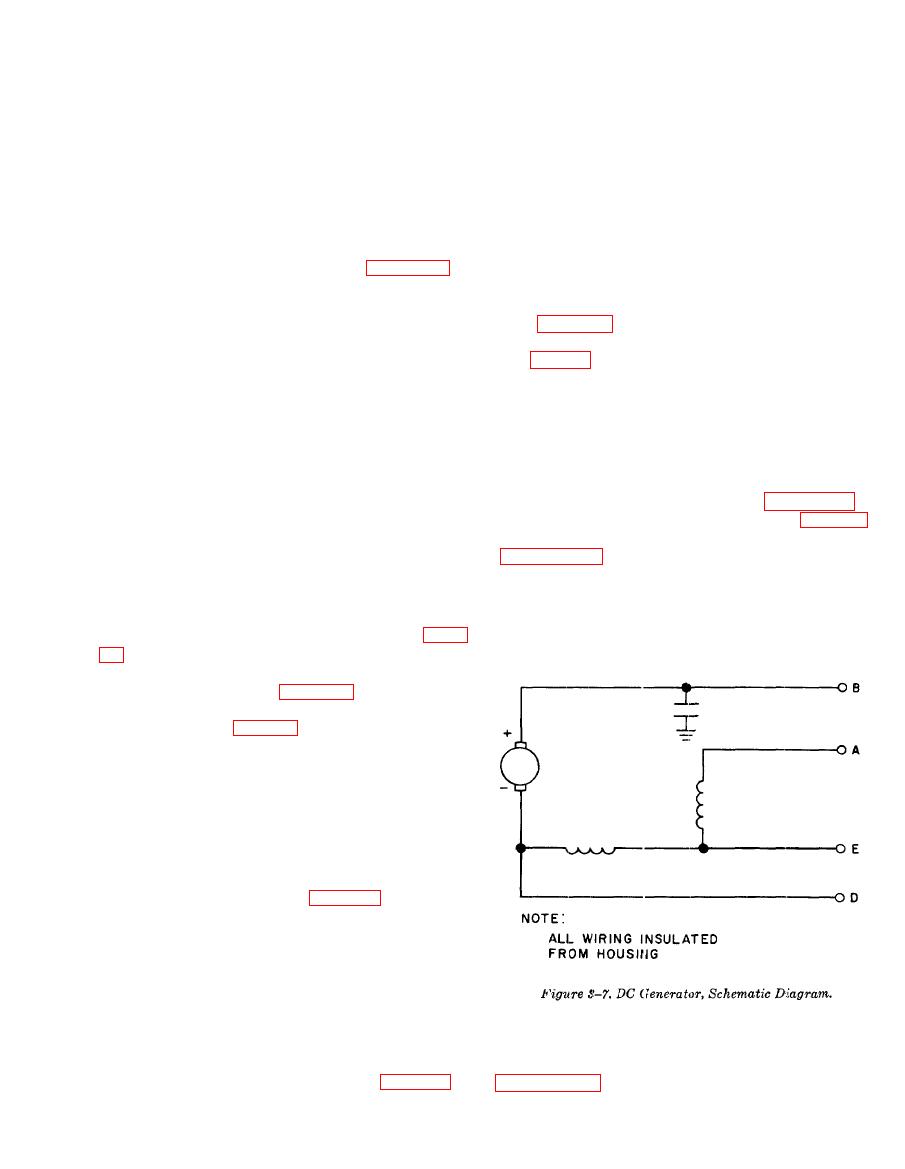
3-6. REASSEMBLY.
under the finished diameter. Finish the surface
Reassembly is basically the reverse of disassem-
by grinding to an inside diameter of 2.0472,
bly. Follow the exploded views (figures 3-1,
plus 0.0003, minus 0.0000 inches. The concen-
3-2, and 3-3), the schematic diagram (figure 3-
tricity between the inside diameter of the bearing
7) and the detailed procedures as described in
bore and both the outermost (4.122-inch) di-
ameter of the stator housing, and the largest
structions.
inside (6.125-inch) diameter of the end bell
must be within 0.002 inch, full indicator reading.
(9) Remove masking shellac and grinding
residue with denatured alcohol (item 8, table
2-3) .
e. Soldering.
(1) If terminals (29, figure 3-1) were re-
placed, use a rosin core solder composed of 100
percent tin (item 9, table 2-3) to solder the ter-
minals to the capacitor leads. This solder has a
melting point of 232 C (450 F).
CAUTION
D o not use an acid solder or an acid
flux, Do not burn insulation when sol-
dering.
(2) For all other soldering operations, use
silver brazing alloy (item 10, table 2-3) com-
posed of 15 percent silver, 80 percent copper,
and 5 percent phosphorous. This solder has a
m e l t i n g range between 650 C and 705 C
(1200 F and 1300 F).
(3) All soft soldering must be done in ac-
cordance with Specification MIL-S-6872B. All
silver brazing must be done in accordance with
a. Generator Stator.
Specification MIL-B-7883B.
(1) If any terminals were removed or re-
(4) After soldering or brazing, clean all
placed, braze terminals to leads as specified in
joints with denatured alcohol (item 7, table 2-3)
