TM 5-6115-631-14&P
NOTE
Observe identification tags when installing internal wires.
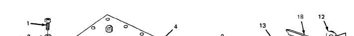
(d) Slide Iockwasher (10) and terminal lug(s) of wire(s) (9) onto stud (8).
(e) Install Iockwasher (7) and nut (6) on terminal (8) and tighten against wire terminal lug.
(f) Position cover (4) on switch box (5) and secure with 16 screws (1), 16 Iockwashers (2)
and 16 flat washers (3).
Figure 4-10. Load Terminal Replacement.
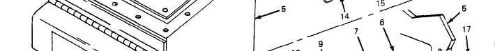
b. Indicator Light and Wire Assembly Repair and Replacement. (See figure 4-11.) There are two
indicator light and wire assemblies on the switch box. This procedure is typical for both. When attach-
ing wires, refer to the schematic inside the switch box (figure 4-7 or 4-8, as applicable). The indi-
cator light and wire assembly is repaired by replacing defective terminals or soldering broken wires.
Soldering shall be done in accordance with TB SIG 222.
(1) Removal.
(a) Remove 16 screws (1, figure 4-11), 16 Iockwashers (2) and 16 flat washers (3)
securing cover (4) to switch box (5) and take cover off switch box.
(b) Remove screw (6), nut (7) and star washer (8) attaching each indicator light wire ter-
minal (9) to its respective switch terminal (10). Take power cable wire (11) and indica-
tor light wire (12) off switch terminal.
4-22