TM 5-6115-628-14&P
NOTE
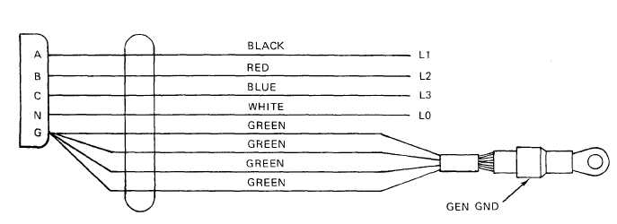
The contacts in the connector end of cable are labeled A, B, C, N, and G.
The individual colored wires at the other end of cable are labeled L0, L1, L2,
L3, and GEN GND.
b. Touch one probe to contact A in connector and touch remaining probe to black wire labeled
L1. Multimeter must indicate continuity. If it does not, cable is open.
c. With first probe still in contact A, touch remaining probe to wires labeled L2, L3, L0, and
GEN GND. Multimeter must not indicate continuity. If it does, cable is shorted.
d. Refer to figure 4-13, and repeat steps b. and c. at connector contacts B, C, and N. In each
case, continuity must exist between corresponding points and only between corresponding
points.
Figure 4-13. Power Cable Wiring Diagram.
e. Connect one multimeter probe to GEN GND lug on cable and touch remaining probe to contact
G in connector. Multimeter must indicate continuity.
f. If continuity test detects any opens or shorts in cable, refer cable to higher level of
maintenance.
4-28.
Switch Box Testing. The power plant switch box assembly is tested by performing a series of
continuity checks on the component parts and internal wiring.
NOTE
All internal switch box wiring is labeled for identification with reference
designations of its points of connection. If labeling has been removed, or is
illegible, tag wires for identification before removing them.
a. Switch Testing. The switch box contains two three-pole, single-throw switches. Testing
procedures are typical for both.
4-27