(1)
(2)
(3)
(4)
TM 5-6115-627-14&P
NOTE
All internal switch box wiring is labeled for identification with reference designations of its
points of connection. If labeling has been removed, or is illegible, tag wires for
identification before removing them.
Remove 24 screws, 24 Iockwashers, and 24 flat washers securing access cover to switch box and
remove cover.
Before testing wires, make sure there are no loose connections or broken terminals. Tighten any loose
connections and refer broken terminals to higher level of maintenance.
Set multimeter controls to prepare unit for continuity testing.
Refer to wiring diagram (figure 4-14) and test continuity of suspect wires between origin and destination
specified in diagram.
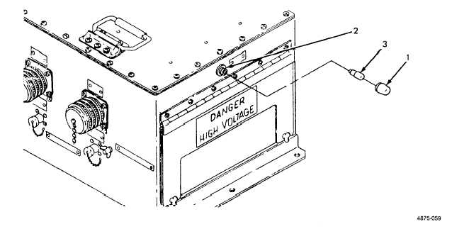
4-29. Indicator Light Lens and Lamp Replacement. (See figure 4-15) There are three indicator
lights on the switch box. Only the lens and lamp may be replaced at unit level maintenance. Replacement
procedures are the same for all three.
a.
b.
c.
d.
Unscrew lens (1, figure 4-15) from housing (2). Lamp (3) will come off together with lens.
Pull lamp (3) out of lens (1).
Insert new lamp (3) into lens (1).
Screw lens (1) into housing (2).
Figure 4-15. Indicator Light Lens and Lamp Replacement.
4-31


