
2-20. Control Box Wiring Harness
a. Inspection. Inspect all wiring insulation for
cracks and frayed places.
b. Testing. To test the lead for continuity,
disconnect each end of a lead from the component to
which it is attached. Touch the probes of a test light
to each end of the lead. If lamp does not light, lead is
defective.
2-21. Terminal Board and Load Stud Power Cable
Inspect the terminal board and load studs for
cracks, breaks, looseness and corrosion.
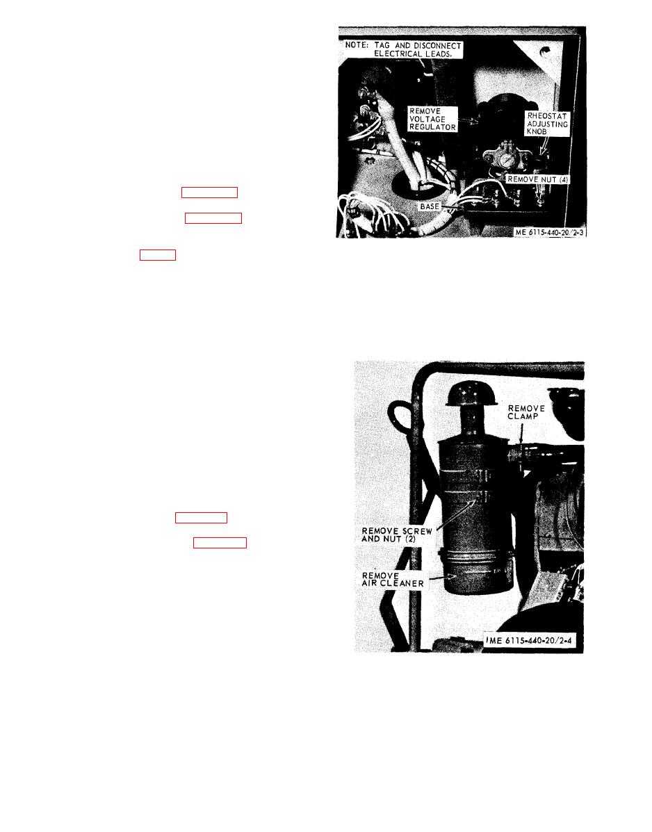
a. Removal. Refer to figure 2-3 and remove the
voltage regulator.
b. Installation. Refer to figure 2-3 and install the
voltage regulator.
c. Adjustment. Turn the voltage regulator rheostat
adjusting knob (fig. 2-3) with a screwdriver until the
output voltage indicated on the voltmeter is correct
(normal reading is 28 volts).
Section IX. FUEL SYSTEM
2-23. General
The fuel system consists of the air cleaner, fuel
strainer, fuel pump, carburetor, fuel selector valve
and fuel tank. The air cleaner is secured to a
mounting plate on the front left end of the engine
flywheel shroud. The fuel pump is connected to an
adapter and primer which is used to help pump the
fuel when an engine has been out of operation for a
long time. The fuel is filtered by a fuel strainer
before it enters the fuel pump. The carburetor is
located directly under the exhaust manifold. The
carburetor is of the updraft single venturi design.
2-24. Air Cleaner
a. Removal. Refer to figure 2-4 and remove the air
cleaner.
b. Installation. Refer to figure 2-4 and install the
air cleaner.
