
TM 11-6125-240-34
c. Procedure.
in (4) above. No variation should recur in the adjust-
ment range specified. Turn off the aircraft ac compo-
(1) Turn the main power switch in the aircraft to
nents and set the voltage adjustment potentiometer so
ON. Check to see that the inverter starts and the
that a 115-volt output is indicated on the voltmeter of
aircraft dc voltmeter indicates 28 volts.
the power test set. Tighten the locknut.
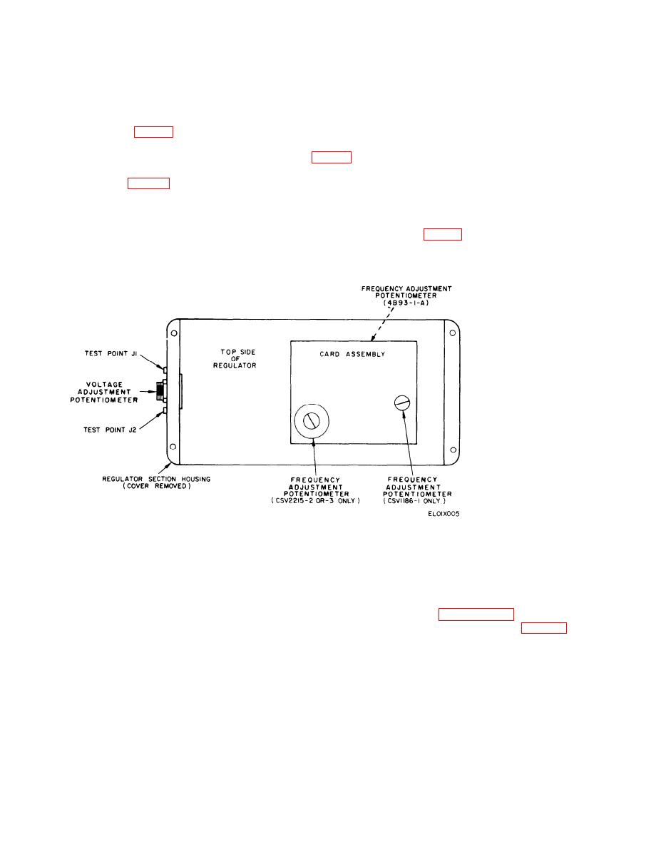
(2) Plug the prods of a power test set into the in-
verter test point jacks (fig. 3-1).
(6) Remove the regulator cover. Operate the in-
verter at no load and turn the frequency adjustment
(3) Set the power test range selector to 150.
(4) Operate the inverter at no load (no ac compo-
regulation, as indicated on the frequency meter of the
nents of the aircraft operating). Loosen the voltage po-
power test set, must be 390 Hz to 410 Hz.
tentiometer's locknut (fig. 3-1 ) and turn through its full
range. Voltage indicated on the voltmeter of the power
NOTE
test set must not be lower than 109 or more than 121.
To reach the frequency adjustment on the
4B93-1-A, the regulator must be removed
(5) Apply a full load to the inverter by turning on
from the spacers (8, fig. 4-5) and flipped over.
all the aircraft equipment that operates from the ac
supplied by the inverter. (Refer to the applicable
The frequency adjustment is located on the
aircraft technical manual.) Repeat the procedure given
underside of the board.
Figure 3-1. Voltage and Frequency Adjustments
(7) Apply a full load and turn the frequency ad-
remove the power test set prods from the inverter test
justment through its full range. No variation should oc-
point jacks. Turn off the aircraft master switch and
cur in the range specified in (6) above. Turn off the
disconnect the external power source from the aircraft.
aircraft components and reset the inverter frequency
3-6. Troubleshooting Table
adjustment to provide a 400-Hz output. Replace the
If the operational test in paragraph 3-5 indicates a
regulator cover.
malfunction, localize it using troubleshooting table 3-1.
(8) Turn on the aircraft ac components one at a
If the procedures in the table fail to correct the fault, or
time until the inverter is fully loaded. Voltage varia-
if a malfunction not mentioned in the table is noted,
tion between no load and full had must be less than 3
volts. The frequency variation must be less than 8 Hz.
refer the inverter to higher category maintenance.
(9) Upon completion of the operational test,
3-2
