
TM 11-6125-240-34
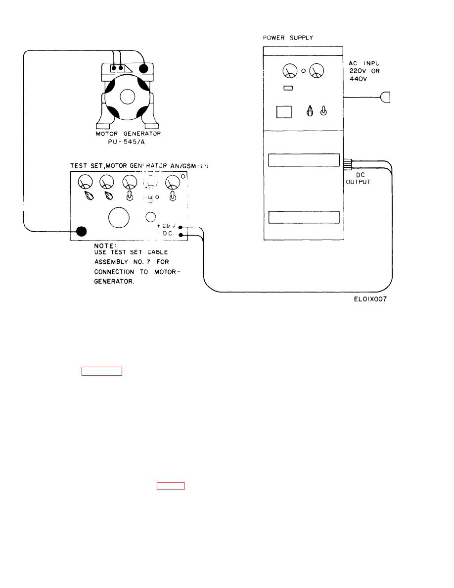
Figure 3-3. Connections for Brush Run-In and Performance Test
3-9. Replacement of Regulator Circuit Card
ment potentiometer is connected directly to the card
Assembly
assembly. If a change of the CSV2215-2 or CSV2215-3
is made, remove the potentiometer from the housing
NOTE
The 4B93-1-A cannot be installed without
along with its associated wiring and utilize the one sup-
modification (para 3-12) to the regulator sec-
plied with the replacement card assembly,
(1) Remove the regulator cover.
tion. This modification can only be performed
at depot level.
(2) Make a small sketch, showing the color coding
of each lead and where it is connected to the other wir-
a. Use the procedure in b below when replacement
ing of the regulator.
of the regulator card assembly is necessary. Note that
regulator card assembly CSV1186-1 (3 piece, sealed
(3) Disconnect the electrical leads of the card as-
with blue epoxy) is no longer maintained. If the in-
sembly.
verter is equipped with this card assembly, universal
(4) Remove the four bolts and washers that secure
type CSV2215-2, CSV2215-3, or 4B93-1-A (1 piece,
the card assembly base to the regulator housing, and
sealed with clear polyurethane) should be used as a
remove it.
replacement. Forward card assembly CSV1 186-1 to
(5) Position the replacement card assembly card
depot maintenance for salvage of usable components.
assembly in the regulator housing, and secure with the
bolts and washers removed in (4) above.
b. On regulators with the CSV1186-1 or 4B93-1-A,
(6) Change over the voltage potentiometer as de-
the voltage adjustment potentiometer (fig. 3-1) is a
separate unit attached to the regulator housing and
scribed above, if necessary.
(7) Attach the leads as indicated in the sketch pre-
fastened to terminals 3,7 and 8 of terminal board TB2
pared in (2) above.
On the CSV2215-2 and CSV2215-3, the voltage adjust-
3-6
