
TM 11-6125-240-34
(2) Slide the new brushes into their respective
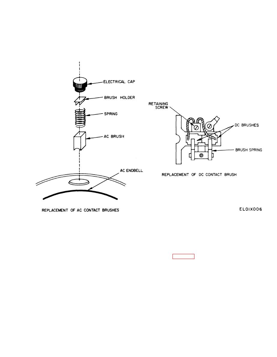
a. Ac Contact Brushes.
positions in the ac endbell. Be sure the curve of the
(1) Remove the four electrical caps and withdraw
brush matches that of the sliprings.
the brush holders, springs, and brushes. Note that two
(3) Secure each brush with an electrical cap.
are straight and two angled. Use like types for replace-
ment.
Figure 3-2. Replacement of Brushes.
the screws removed in (2) above,
b. Dc Contact Brushes.
(6) Replace and secure fan cover.
(1) Remove the fan cover.
c. Brush Run-In and Preseating. Preheating and
CAUTION
final brush seating must be accomplished after the
D C brushes are critical items. Use only
brushes have been installed. Connect the inverter as
brushes specified for use on this equipment.
(2) Remove the retaining screws from the leads of
quarter rated output) for approximately two hours.
each of four dc contact brushes.
Then check the brush contact area for shading and ap-
(3) Lift up the brush springs and pull the brushes
ply 2500VA (full load) until the requirements in (1) and
clear of their holders.
(2) below are met. Minor variations in shading may ap-
(4) Install new brushes by lifting the brush
pear occasionally, and should be disregarded.
springs and sliding the new brushes into the holders.
(1) Ac contact brushes: 50 percent of brush con-
The curved face of the brush must fit the curve of the
tact area.
commutator. Make certain that they slide easily, with-
(2) DC contact brushes: 100 percent in the direc-
out binding, and that the springs engage the center
tion of armature rotation, 75 percent of brush thick-
point of the brushes without interference from the
ness.
leads.
(5) Secure the brush leads to the dc endbell with
3-5
