
TM 9-6115-730-24
0042
REMOVAL - Continued
7. Remove three screws (Figure 1, Item 8), lockwashers (Figure 1, Item 9), and washers (Figure 1, Item 10).
8. Remove two screws (Figure 1, Item 11), lockwashers (Figure 1, Item 12), and washers (Figure 1, Item 13).
9. Remove five screws (Figure 1, Item 14), lockwashers (Figure 1, Item 15), and washers (Figure 1, Item 16).
10. Slide Control Box (Figure 1, Item 17) out of generator set and place on suitable work surface.
11. If necessary, remove two screws (Figure 1, Item 18), lockwashers (Figure 1, Item 19), washers
(Figure 1, Item 20), and brace (Figure 1, Item 21).
END OF TASK
DISASSEMBLY
NOTE
Disassembly of the control panel can be accomplished on or off the generator set, however
access to some components may be improved if control box is removed. Table 1 lists specific
steps for disassembly and assembly of significant control box components.
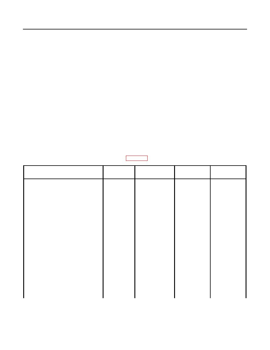
Table 1. WP 0042 Guide.
FIGURE 2
DISASSEMBLY
ASSEMBLY
RELATED
NAME
ITEM
STEPS
STEPS
STEPS
AC Transformer Box (ATB) A5
45
1, 2, and 14
16
Alarm Reset (AR)
73
1, 2, and 20
10
Auxiliary Fuel Pump Relay (AFPR)
72
1, 2, and 20
10
Bus Transformer Box (BTB) A6
19
1, 2, and 7
23
Cool Down Relay (CDR)
71
1, 2, and 20
10
Dead Bus Relay, High Voltage
79
1, 2, and 21
9
Sensing (DBHI)
Dead Bus Relay, Low Voltage
78
1, 2, and 21
9
Sensing (DBLO)
Digital Voltage Regulator (DVR) A3
98
1, 2, and 26
4
Relay Field Flash (KFF)
75
1, 2, and 20
10
Generator Fault Relay (GFR)
74
1, 2, and 20
10
Ground Fault Circuit Interrupter
42
1, 2, and 13
17
(GFCI)
Load Sharing Module (LSM) A4
28
1, 2, and 9
21
Adjustment
1 thru 4
