TM 9-6115-730-24
0003
GENERATOR
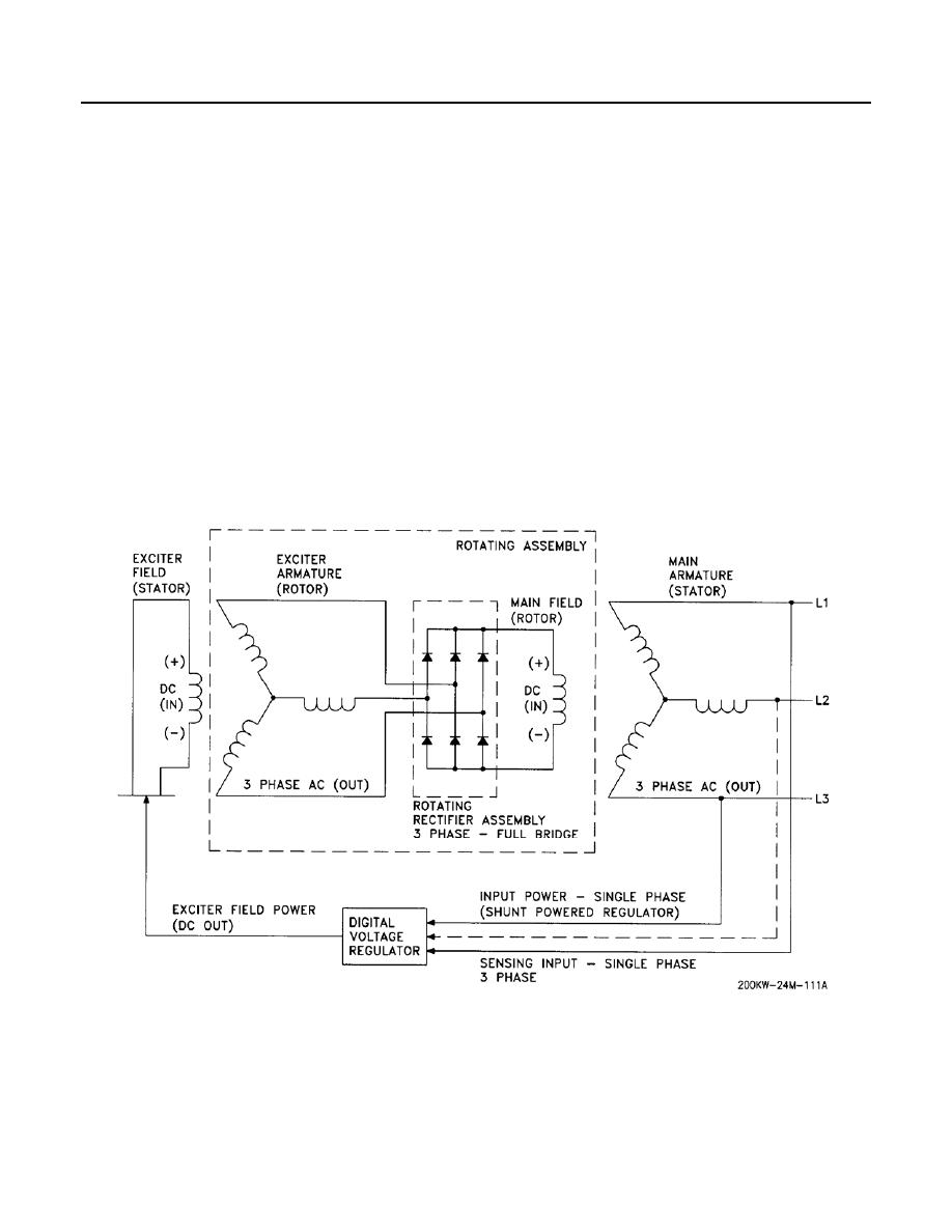
The generator (Figure 13) is a brushless, self-excited, externally voltage regulated, synchronous AC generator.
The generator consists of five major components: the main stator (armature); main rotor (field); exciter stator
(field); exciter rotor (armature); and rectifier assembly. The DVR controls generator output. The generator exciter
consists of a stationary field and a rotating armature. The DVR applies voltage to the stationary field (exciter
stator). The exciter armature generates an AC voltage that is rectified by the rotating rectifier assembly,
converting it to a pulsating DC signal. This DC is applied to the main rotor (field). As the generator shaft rotates,
the main rotor (field) induces a voltage into the main stator (armature). The main stator's voltage output is
sampled and compared to the programmed desired value in the DVR The exciter field power is increased or
decreased in order to regulate the main stator output to the desired value. There are four poles on the generator.
There are two + poles and two - poles. During each revolution of the generator, two complete sine waves are
produced by the alternating +, -, +, - poles. For 60 Hz operation, the generator shaft will have to turn 60 2
revolutions per second (rps) = 30 rps. Engine speed is in rpm, therefore 30 rps x 60 seconds per minute = 1800
rpm engine speed required for 60 Hz operation. 50 Hz operation is the same process (or 50 60 x 1800 = 1500
rpm). Note that an excitation is required to get the process started. This excitation, also known as a Field Flash, is
described in the DC Power Distribution section. Since there is no permanent magnet structure in the
generator assembly, a voltage spike is applied to the exciter field (stator) to ensure that the regulation process
gets off to a good start. This generator is built with 2/3 pitch main stator windings and full Amortisseur (damper)
windings. These features make the generators suitable for parallel operation when used with the proper
voltage and load regulating devices.
Figure 13. Generator.


