TM 9-6115-730-24
0003
DIGITAL VOLTAGE REGULATOR (DVR A3) MODULE
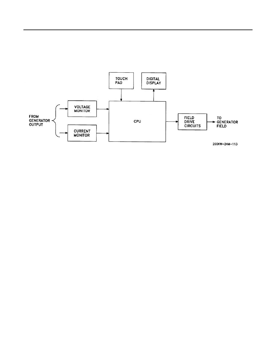
DVR A3 (Figure 10) is a microprocessor based, digital voltage regulator. The regulator is specifically designed to
regulate the output voltage of a generator in an engine/generator set arrangement. The DVR consists of a touch
pad, digital display, CPU, voltage and current monitoring circuits and field drive circuits.
Figure 10. Digital Voltage Regulator.
Touch Pad and Digital Display
The touch pad allows the user to input operating and alarm parameters into the DVR and to check alarm conditions
past and present. When power is applied, :01 is displayed. This is the generator output Voltage Parameter. The
touch pad allows the user to access the following data, which is displayed on the digital display:
Voltage
3 Phase kVAR
Hours
Current
Software ID
Reactive Output Power
Latest Fault
Generator Real Current
Previous Fault
Exciter Field Current
CPU
The CPU contains the program which monitors generator output voltage and current, determines how much drive
current to supply the generator field in order to maintain desired output voltage, and monitors generator operation.
Alarm conditions are displayed on the digital display.
Voltage and Current Monitoring Circuits and Field Drive Circuits
The generator output is monitored for voltage and current. This data is input to the CPU where the data is
compared to the desired output from the generator. The field drive circuits provide field excitation current for the
generator, which regulates the output voltage of the generator.


