
TM 9-6115-729-24
0040
NOTE
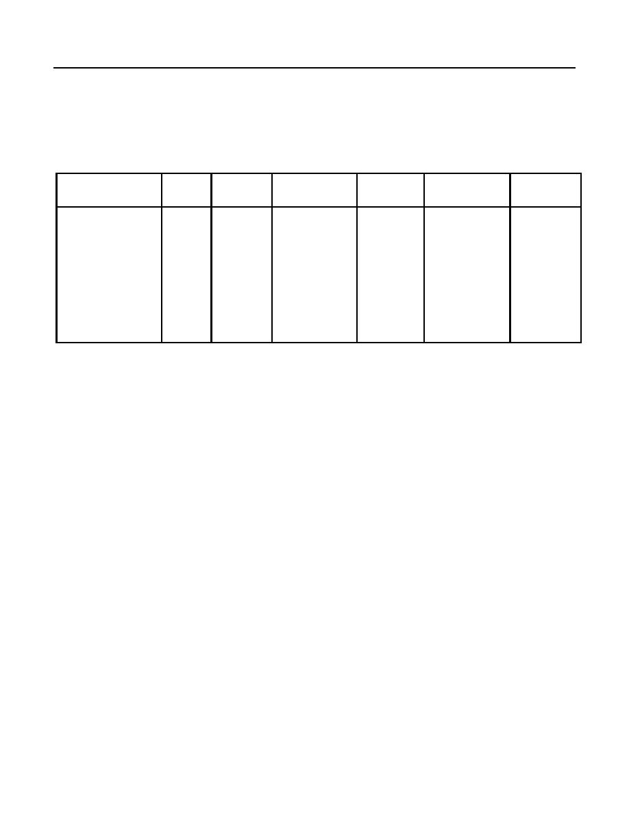
Table 1 lists removal/installation steps for significant components.
FIGURE REMOVAL DISASSEMBLY ASSEMBLY INSTALLATION
TESTING
NAME
ITEM
STEPS
STEPS
STEPS
STEPS
Generator Set
12
1 thru 3
1 and 2
20 and 21
1 thru 5
-
Control (GSC)
Alarm Module A2
55
1 thru 3
12
10
1 thru 4
-
VOLTAGE Adjust
73
16
-
-
6
1 thru 7
Potentiometer
FREQUENCY Adjust 75
16
-
-
6
1 thru 10
Potentiometer
REMOVAL
1. Ensure generator set is fully stopped, ENGINE CONTROL switch is set to OFF/RESET, Battery Disconnect
Switch is set to OFF, and DEAD CRANK SWITCH is set to OFF before proceeding.
2. Turn two latches (Figure 1, Sheet 1, Item 1) and open control box door (Figure 1, Sheet 1, Item 2). Refer to
Table 1 for removal/installation steps for specific control box panel assembly items. Tag and disconnect
wiring to components before removing them.
3. Release three studs (Figure 1, Sheet 1, Item 3) and lower control box panel assembly (Figure 1, Sheet 1,
Item 4).
NOTE
Control box panel assembly components can be removed without removing control box panel
assembly.
4. Remove three nuts (Figure 1, Sheet 2, Item 5) to remove control box panel assembly (Figure 1, Sheet 1,
Item 4) from hinges (Figure 1, Sheet 3, Item 6).
5. Unhook holder (Figure 1, Sheet 1, Item 7) from control box (Figure 1, Sheet 1, Item 8) and remove control box
panel assembly (Figure 1, Sheet 1, Item 4) from control box.
