
ARMY TM 9-6115-673-13&P
AIR FORCE TO 35C2-3-512-1
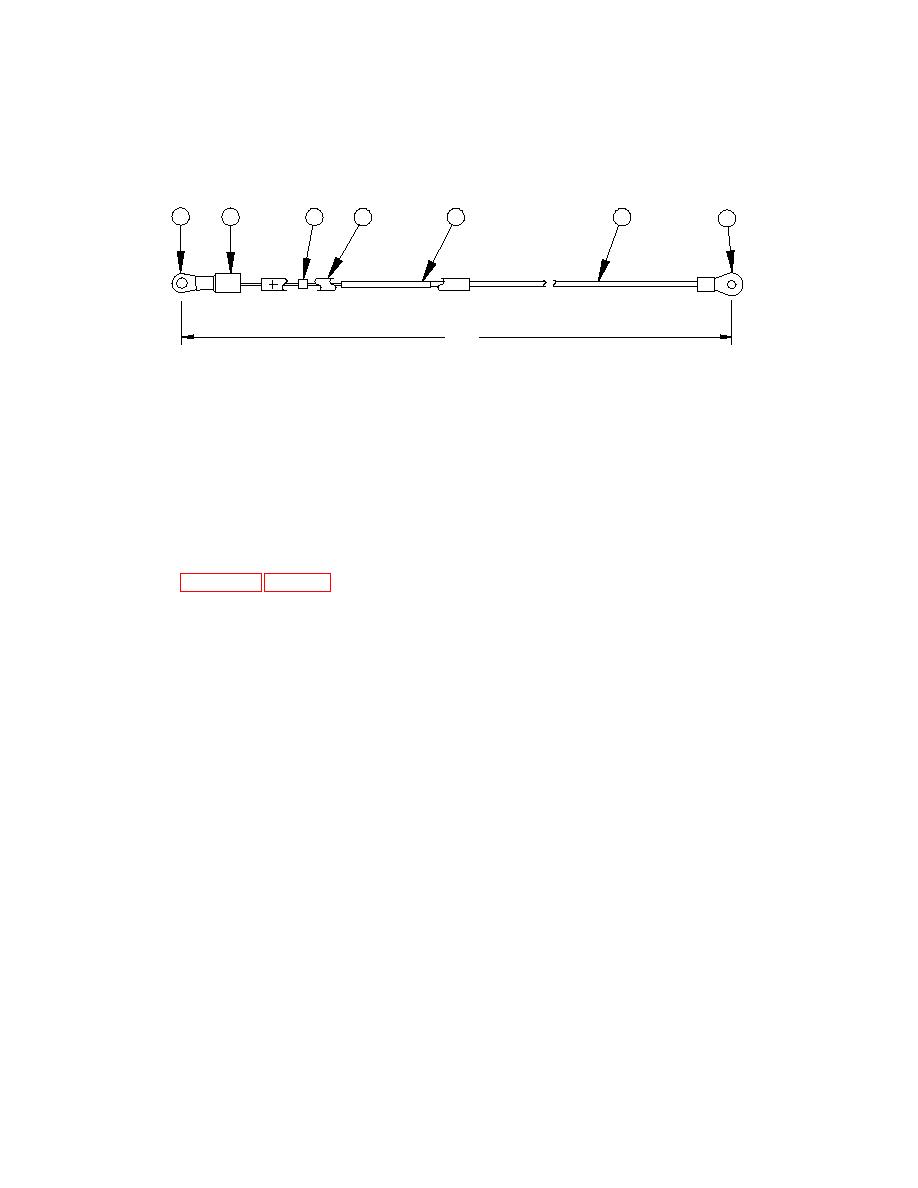
1
2
3
5
6
4
7
TB1-1
S2-S
13.50
[342.90]
NOTES:
PROCEDURES:
1. Dimensions are shown in inches and
1. Cut wire (6) to length indicated then strip
dimensions in [ ] are in millimeters.
0.50 [13] from ends of wire.
2. Refer to Appendix F, Fig. F-28 for materials
2. Install insulation sleeving (2) by sliding over
required.
positive wire of diode (3).
3. Crimp terminal lug (1) to positive wire of diode
(3).
4. Install insulation sleeving (2) over terminal lug
(1), and heat shrink to a firm fit.
5. Slide splice (5) over negative wire of diode (3)
and crimp.
6. Slide wire (6) into splice (5) and crimp.
7. Slide insulation marker (4) over wire (6),
splice (5) and diode (3), then heat shrink to
a firm fit.
8. Slide terminal lug (7) onto wire (6) and crimp.
9. Mark the appropriate wire number which will
consist of the `FROM' termination, a double-
headed arrow (↔), and the `TO' termination.
