ARMY TM 9-6115-671-14
AIR FORCE TO 35C2-3-446-32
MARINE CORPS TM 09249A/09246A-14
5-32
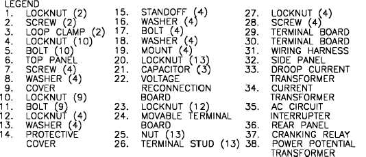
FIGURE 5-3. OUTPUT BOX ASSEMBLY (SHEET 2 OF 2)
5.8.2
Voltage Reconnection Terminal Board TB1.
a. Inspection.
Inspect voltage reconnection terminal board (22, Figure 5-3) for cracks, corrosion, stripped threads,
bent or broken terminal studs, and other obvious damage.
b. Replacement.
(1)
Shut down generator set, paragraph 2.11.2.
(2)
Open BATTERY ACCESS door (Figure 1-2), and disconnect negative battery cable.
(3)
Open output box and load terminal board access doors (Figure 1-2).
(4)
Remove locknuts (12, Figure 5-3), washers (13), and protective cover (14) from standoffs (15).
(5)
Remove standoffs (15), washers (16), bolts (17), washers (18), and mounts (19) from rear panel
(36) and voltage reconnection board (22).
(6)
Tag electrical cables, main generator cables, and capacitors (21) at voltage reconnection board
(22). Remove locknuts (20), cables, and capacitors (21) from voltage reconnection board.
(7)
Remove voltage reconnection board (22), with moveable terminal board (24) attached, from rear
panel (36).
(8)
Remove locknuts (23) and moveable terminal board (24) from terminal studs (26).
(9)
Remove nuts (25) and terminal studs (26) from voltage reconnection board (22).
(10) Install terminal studs (26) and nuts (25) on voltage reconnection board (22). Torque nuts to 150-
200 in-lb (16.9-22.6 Nm).
(11) Install moveable terminal board (24) and locknuts (23) on terminal studs (26).
(12) Position voltage reconnection board (22) and moveable terminal board (24) on rear panel (36).