ARMY TM 9-6115-671-14
AIR FORCE TO 35C2-3-446-32
MARINE CORPS TM 09249A/09246A-14
4-193
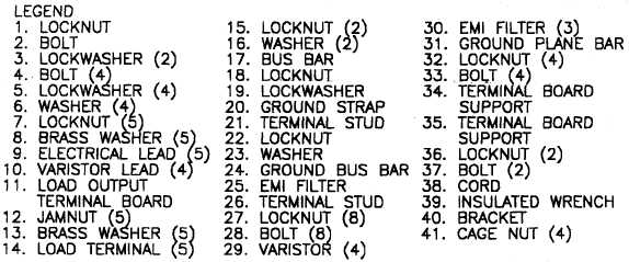
FIGURE 4-29. LOAD OUTPUT TERMINAL BOARD ASSEMBLY (SHEET 2 OF 2)
(7)
Inspect cage nuts (41) for cracking or stripped threads.
(8)
Replace damaged and defective parts.
(9)
Close load output terminal board access door.
c. Repair.
Repair load output terminal board assembly by replacing damaged or defective wires, load terminals, EMI
filters, and varistors.
d. Installation.
(1)
Install bracket (40, Figure 4-29), insulated wrench (39), cord (38), bolts (37), and locknuts (36) on
terminal board support (34).
(2)
Install terminal board supports (34 and 35), bolts (33), and locknuts (32) on generator set.
NOTE
Position EMI filters to align with mounting holes for load terminals L1, L2, and
L3 respectively.
(3)
Install ground plane bar (31), EMI filters (30), varistors (29), bolts (28), and locknuts (27) on load
output terminal board (11).
(4)
Connect varistor leads (10) to varistors (29).
(5)
Install terminal stud (26), EMI filter (25), ground bus bar (24), washer (23), and locknut (22).
(6)
Install terminal stud (21), ground strap (20), lockwasher (19), and locknut (18) on load output
terminal board (11). Do not tighten locknut.


