TM 9-6115-664-13&P
c.
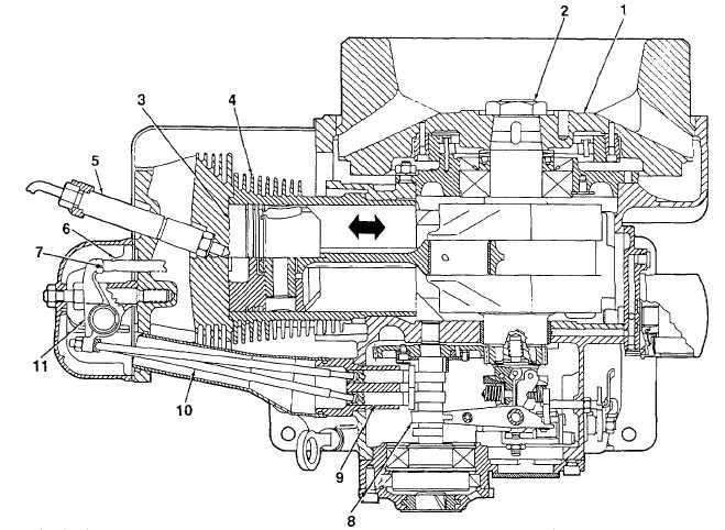
Power Stroke. The combustion of the fuel and air mixture forces the piston (3) downward, turning the
crankshaft (2). The crankshaft is coupled to the alternator shaft and drives the alternator.
d.
Exhaust Stroke. As the crankshaft (2) turns, it forces the piston (3) to again rise to its highest point. Once the
piston begins to rise, the exhaust valve (6) opens. Exhaust gases are forced out of the cylinder (4) as the piston rises.
The exhaust valve closes just before the piston reaches its highest point.
e.
Intake Stroke. As the piston (3) move downward, the inlet valve (7) opens. Air is drawn through the open inlet
valve and into the cylinder (4). The inlet valve closes before the piston reaches the end of its stroke. The piston moves
upward once more to repeat the combustion cycle.
f.
Inlet and Exhaust Valve Operation. Inlet and exhaust valve (6, 7) movement is controlled by lobes on the
camshaft (8). As a camshaft lobe rotates, it forces a tappet (9) to rise, pushing upward on the mating push rod (10). The
push rod forces the rocker arm (11) to rock, pressing down on the inlet/exhaust valve, forcing that valve to open. Air
enters the chamber (inlet valve) or exhaust gases exit (exhaust valve) as appropriate.
1. Flywheel
5. Fuel Injector
9. Tappet
2. Crankshaft
6. Exhaust Valve
10. Push Rod
3. Piston
7. Inlet Valve
11. Rocker Arm
4. Cylinder
8. Camshaft
Figure 1-9. Engine Combustion Cycle (Top View Cross Section)
1-21