TM 9-6115-664-13&P
1-20. APU COOLING AND EXHAUST SYSTEM.
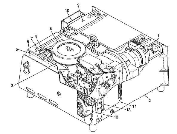
a. Air Cooling System. Cool air is drawn into the APU box by twin fans. Air enters the box through a duct (2,
Figure 1-7) located in the base of the box. The air feeds the alternator (1) and engine flywheel, and air flows across the
windings and exits the box. The engine air flows thru the cylinder fins (3) and exits the box through the engine head
access door (5). Additional cool air enters the box from ports (6) located behind the nose piece. This air is for box cooling
and combustion air.
b.
Engine Exhaust. Hot exhaust air and fumes are passed from the engine exhaust port to an engine silencer
(9), through a curved exhaust pipe (10), and out to the atmosphere.
1. Alternator
6. Air Inlet Port
10. Exhaust Pipe
2. Air Inlet Duct
7. Air Inlet Hose
11. Oil Filter Access Door
3. Engine Cylinder Fins
8. Engine Air Filter
12. Ventilation Fan
4. Air Duct Baffling
9. Engine Silencer
13. Engine Oil Cooler
5. Engine Head Access Door
Figure 1-7. Cooling and Exhaust System
1-19