TM 9-6115-664-13&P
b.
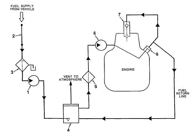
An electric fuel pump (1, Figure 1-6) draws fuel from the vehicle to the APU through an interface fuel line (2).
The fuel passes through a fuel filter water separator (3), which removes contaminating micro particles and separates
water from the fuel flow. Water collects in the base of the fuel filter water separator and may be drained by turning a drain
knob. The filtered fuel enters the electric fuel pump (1) and flows to a fuel float valve assembly (4). The float valve bowl
holds six ounces of fuel to provide three minutes of APU run time. This three minute period allows the operator to switch
from the vehicle fuel supply to an auxiliary fuel supply while the APU is operating. The float valve bowl also functions as
the fuel return location and de-aeration site. Fuel level is maintained in the bowl by means of the float valve.
c.
Fuel flows from the fuel float valve assembly (4), out of the fuel module, and into a secondary in-line fuel filter
(5). The in-line fuel filter is mounted on a bracket at the engine flywheel housing. Filtered fuel passes from the in-line
filter to the engine's mechanical fuel pump (6).
d.
When the control panel START/PRIME RUN/OFF switch is placed in the START position, a start/stop solenoid
is energized, allowing fuel to flow to the engine fuel injection pump (8). The fuel injection pump provides pressurized fuel
to operate the engine fuel injector (7). The fuel circuit is completed when excess fuel is returned to the fuel float valve
assembly (4).
1. Electric Fuel Pump
4. Fuel Float Valve Assy
7. Fuel Injector
2. Interface Fuel Line
5. In-Line Fuel Filter
8. Fuel Injection Pump
3. Fuel Filter Water Separator
6. Mechanical Fuel Pump
Figure 1-6. Fuel System Diagram
1-18


