TM 9-6115-664-13&P
Section I. DESCRIPTION AND USE OF OPERATORS
CONTROLS AND INDICATORS
2-1. OPERATORS CONTROLS AND INDICATORS.
Prior to placing the APU into operation, personnel must be familiar with the location and function of all switches,
controls, and indicators. Controls and indicators required for APU operation are identified in the following illustrations.
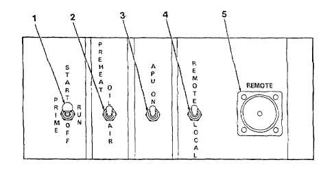
1
START / PRIME RUN / OFF Switch (A1-S4) Three
position switch that controls APU operation.
START position activates engine starter. Spring
loaded. Must be held in place.
PRIME RUN position cuts electrical power to
starter. Energizes all circuits required for normal
operation. When unit is not running, fuel pump
is energized to prime fuel system.
OFF position cuts electrical power to the engine
shutdown solenoid, causing APU shutdown.
2
PREHEAT OIL / AIR Switch (A1-S2) Activates
engine air or oil glow plugs for cold weather starts.
Spring loaded.
3
APU ON Switch (A1 -S3) Energizes latching relay
A1-K1, turning on the alternator and closing the
contactor.
4
REMOTE
/
LOCAL
Switch
(A1-S1)
Switches
operation of APU from local control panel to remote
control panel.
5
REMOTE
Panel
Electrical
Connector
(A1-J2)
Connection point for remote control panel electrical
cable.
Figure 2-1. Controls and Indicators
(Sheet 1 of 4)
2-2