ARMY TM 9-6115-645-24
AIR FORCE TO 35C2-3-444-12
MARINE CORPS TM 09244A/09245A-24/2
d.
Inspect cap for cracks, corrosion or broken chain.
e.
Inspect gasket for tears and deterioration.
f.
Replace any defective part.
g.
If no repair is needed, connect negative battery cable and dose battery access door.
2-63.2 Removal.
a.
Shut down generator set.
b.
Open battery access door and disconnect negative battery cable.
c.
Remove control box top panel, paragraph 2-15.1.
d.
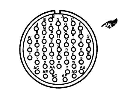
Loosen rear outer ring and plastic insert from diagnostic connector (60, FIGURE 2-14).
e.
Tag and disconnect electrical leads to diagnostic connector (60) by inserting Removal. tool into pins of
connector.
f.
Remove screws (58) and nuts (59).
g.
Remove diagnostic connector cap (61), diagnostic connector (60), and gasket (62).
2-63.3
Installation.
a.
Install diagnostic connector (60, FIGURE 2-14), gasket (62), and cap (61) with screws (58) and nuts (59).
b.
Connect electrical leads to diagnostic connector (60) by using insert tool and remove tags.
c.
Install plastic insert and tighten rear outer ring on connector.
d.
Install control box top panel, paragraph 2-15.4.
e.
Connect negative battery cable. Close battery access door.
FIGURE 2-17. Diagnostic Connector Pin Positions
Change 2 2-93