ARMY TM 9-6115-645-24
AIR FORCE TO 35C2-3-444-12
MARlNE CORPS TM 09244A/09245A-24/2
2-58 REVERSE POWER RELAY.
2–58.1
a.
b.
2-58.2
a.
b.
c.
d.
e.
f.
g.
Inspection.
Shut down generator set.
Inspect relay for cracked casing, burned or broken terminals, and other damage.
Testing.
Shut down generator set.
Open battery access door and disconnect negative battery cable.
Release control panel by turning two fasteners and lower control panel slowly.
Disconnect and insulate wires 158B and 158C from terminal 1, and 161A and 161 B from terminal 2 of reverse
power relay.
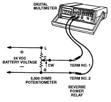
Mark a 5,000 ohm potentiometer as follows:
Center terminal = C
Two outside
terminals = L and R
Voltage polarity is very important to prevent damage to generator set.
Set up a test circuit as shown in FIGURE 2-16. Connect 24 VDC source to terminals L and R of potentiometer.
Connect a wire between terminal C of potentiometer and terminal 1 of reverse power relay. Connect a second
wire between terminal R of potentiometer and terminal 2 of reverse power relay. Set multimeter for DC volts
and connect positive lead of multimeter to terminal 1 and negative lead to terminal 2 of reverse power relay.
Adjust 5,000 ohm potentiometer to full counterclockwise position. Multimeter should indicate O volts.
FIGURE 2-16. Reverse Power Relay Test Set-up
2 - 8 9