ARMY TM 9-6115-644-24
AIR FORCE TO 35C2-3-446-12
MARINE CORPS TM 09249A/09246A-24/2
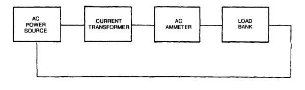
FIGURE 4-6. Testing Current Transformer
g. Repeat steps d, e, and f using phase window B and secondary terminals B1 and B2.
h. Repeat steps d, e, and f using phase C window and secondary terminals C1 and C2.
i.
Replace current transformer if multimeter indication in any phase is other than stated in step f.
j.
Remove current transformer from test circuit.
k. Install current transformer, paragraph 4-11-3.
4-11-3 Installation.
a.
b.
c.
d.
e.
f.
g.
h.
Install current transformer (31, FIGURE 4-5) with screws (29), flatwashers (30), and nuts (28).
Wrap main generator cables around current transformer (31) and droop current transformer (34) using same
number of wraps noted during removal.
Connect main generator cables to voltage reconnection board (18) and remove tags.
Connect electrical leads to current transformer (31) and remove tags.
Close output box and right side engine access doors.
Install output box top panel, paragraph 4-8-2, step j.
Install control box assembly, paragraph 2-19-4.
Connect negative battery cable. Close battery access door.
4-12 DROOP CURRENT TRANSFORMER
4-12-1 Removal.
a. Shutdown generator set.
b. Open battery access door and disconnect negative battery cable.
4-22