
TM 55-6115-491-40
SECTION I
INTRODUCTION
Supply Code 31435. Sections I through IV contain
1-1. GENERAL INFORMATION.
instructions for this model. Instructions for additional
1-2. This technical manual comprises general support
models will be provided in Section V by use of difference
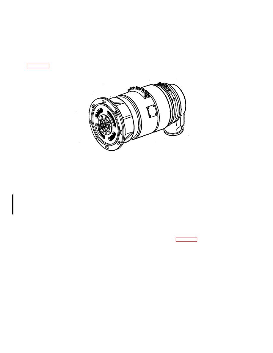
maintenance instructions for Generator Model 3122C-
data sheets.
002 (figure 1-1), manufactured by Lear Siegler, Inc.,
Power Equipment Division, Cleveland, Ohio, Federal
Figure 1-1. Generator Model 31220-002.
1-3. REPORTING OF IMPROVEMENTS.
1-9. DESCRIPTION.
1-4. The individual user is encouraged to report errors,
1-10. This generator provides both alternating-current
omissions, and recommendations for improving this
and direct-current outputs.
The alternating-current
publication. Reports should be submitted on DA Form
output is rated at 120/208 volts, 375 to 425 cps, 3 phase,
2028 (Recommended Changes to DA Publications) and
20 KVA, with a power factor of 0.75 to 1.0 when driven at
forwarded directly to: Commander, US Army Aviation
7,500 to 8,500 rpm. The direct-current output is 28 volts,
Systems Command, ATTN: AMSAV-FC, PO Box 209,
90 watts at 8000 rpm.
1-11. The alternating-current portion of the generator is
St. Louis, Missouri 63166.
housed in the stator housing. It consists of an exciter
section and a main output section. The exciter provides
1-5. PURPOSE OF EQUIPMENT.
the electrical output to energize the alternator field under
1-6. The generator is designed to supply electrical
control of an external voltage regulator and control
energy for aircraft alternating current systems.
system. The external regulator connects to terminals Fl,
1-7. EQUIPMENT RECORDS.
A+, and A-, F2 (figure 1-2). The main generator output is
1-8.
The Army Maintenance Management system
available at terminals T1 through T6 on the main output
established in TM 38-750 applies to this equipment. The
terminal board.
applicable forms as required by TM 38-750 shall be
used.
Change 1 1-1
