and the stop pin on the carburetor. The clearance
will cause the lever to bounce back from the stop
pin, rather than jam against the pin, when a load is
suddenly applied to an idling engine. This will
eliminate excessive wear on the threads of the
control rod and ball joints.
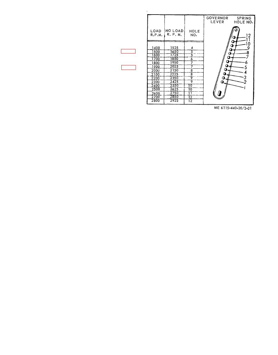
b. The governor lever is furnished with 12 holes
for attaching the governor spring as shown in figure
2-21. It is very important that the spring is hooked
into the proper hole to suit the speed at which the
engine is operated. The governor lever chart (fig. 2-
21) shows the full load and no load speeds of the
engine and the hole corresponding thereto. The full
load speed will be from 150 to 125 revolutions less
than the no load speed. As an example; if the engine
is to be operated at 2000 revolutions per minute
under load, the spring should be hooked into the 8th
hole in the governor lever and the spring tension
adjusted by means of the adjusting screw connected
to the spring, to run 2150 revolutions per minute,
without load. The speed at full load will then be
Figure 2-21. Governor lever adjustment chart.
a p p r o x i m a t e l y 2000 revolutions per minute. A
2-47. Engine Air Shroud and Air Deflector
tachometer or revolution counter should be used
a. General. The engine air shrouds and air
a g a i n s t the crankshaft while making this ad-
deflectors are installed around the cylinder block
justment.


