
TM11-6125-256-34
(1) With the wipers set for maximum resistance,
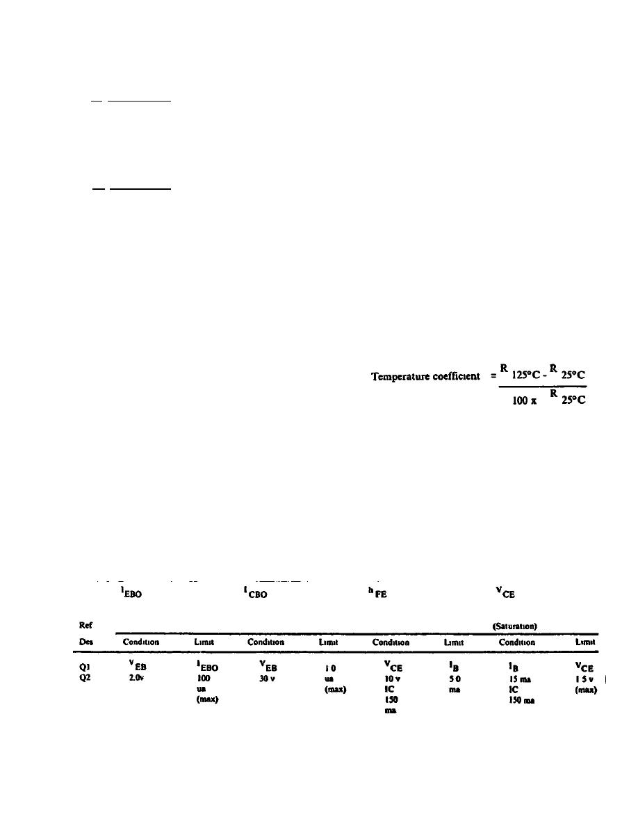
4-17. Transistors
place the potentiometer under test in a controlled
a. 4B48-6-A. To check silicon transis-
ambient temperature of 77 F (25C) 5F (9C) for 30
tors Q1 and Q2 (53, fig. 4-5), set up the
conditions specified in table 4-4 and check minutes and measure and record the resistance value
for the specified values, using Transistor
Test Set TS-1836()/U. To check power tran-
sistors Q3 through Q6 (11 and 12, fig. 4-5),
(2) With the controlled ambient temperature
see table 4-4.
adjusted to 257F (125C), heat the potentiometer under
b. 4B93-1-A. To check transistors Q1
through Q11 (7, 14, 16, 17, and 29, fig. 4-5.1), test for 30 minutes and measure and record the resistance
set up conditions specified in table 4-4.1 value
and check for specified values, using the
TS-1836()/U.
4-18. Resistors. Using resistance bridge
ZM-4B/U, measure the values of resistance
(3) Using the resistance values obtained in steps (1)
specified in table 4-5 or 4-5.1.
and (2), calculate the temperature coefficient of
a . G r o u n d c h e c k r e s i s t o r s R 1 2 and R13
resistance by means of the following formula (where R =
(20, fig. 4-5) by applying 750 volts ac,
60 Hz, between the terminals and the case
resistance)
for one second.
b With the wipers placed for maximum resistance and
terminals shorted together, ground check potentiometers
R14 and R15 (11 and 28, fig. 4-5) or R5
and 23 (13 and 1, fig. 4-5.1) by applying
500 volts ac, 60 Hz between the terminals
and the case for one minute.
d The temperature coefficient calculated in step c
c Check the temperature coefficient of
the potentiometers as follows:
should not exceed 20 ppm per degree (C)
