
TB 9-6115-643-13
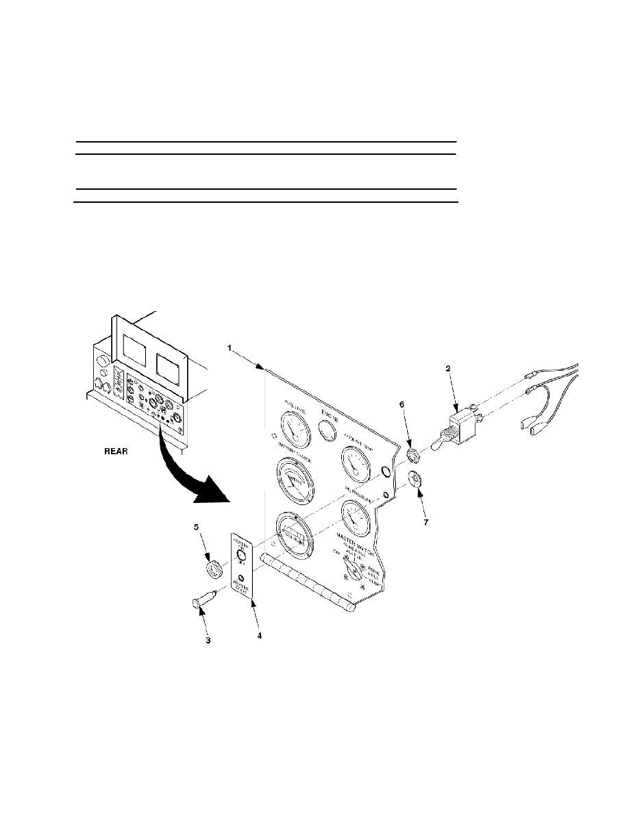
2.
Connect all electrical leads to indicator light (3).
3.
Install switch (2), mounting nut (6), knurled nut (5), and reconnect electrical leads to switch (2).
4.
Raise and secure control panel (1).
5.
Reconnect negative battery cable.
INSPECTION OF OPERATING PLATE, FUNCTION CODE PLATE, AND ID PLATE
1.
Inspect lable for illegible instructions, dents, cracks, etc.
REPLACEMENT OF OPERATING PLATE, FUNCTION CODE PLATE, AND ID PLATE
1.
Open operation panel. Using electric drill with 1/8" drill bit, drill each of the rivets and punch out.
2.
Template should be placed approximately 1" from top enclosure of the control panel door and approximately 4"
from left edge of the control panel door.
3.
Install plates using blind rivets.
