TB 11-6115-741-24
Special Maintenance Requirements
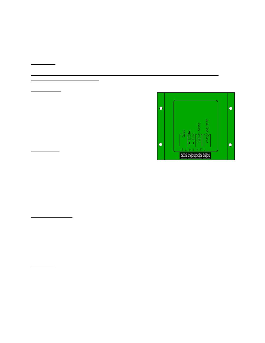
(A1) and Quad Winding Problem
6.2.1 Overview
The 5 and 10 kW TQG's use a "Quad" winding circuit to
provide a no-load voltage source to the voltage regulator
(A1). The "Quad" winding, designated as Q1-Q2, is a
separate winding within the main alternator stator that is
connected directly to the A1 "Quad" circuit (terminals 7 and
8.) The A1 uses a full-wave bridge to rectify the quad
winding input voltage.
6.2.2 Problem
The A1 full-wave bridge rectifier diodes short out and cause
catastrophic failure of the "Quad" winding. This renders the generator set inoperative and necessitates
replacement of the entire main stator and A1. In many field cases the A1 bridge rectifier circuit problem
remains undetected and the main stator is replaced and put back into service. This causes immediate
failure of the new stator. Given the relatively low cost of the A1 and the relatively high cost of the main
stator and given the excessive labor cost and downtime associated with main stator failures, it is necessary
to protect the "Quad" winding from damage in the event of bridge rectifier circuit failure and to establish
some "Quad" circuit troubleshooting guidelines to ensure proper diagnosis of A1/"Quad" circuit
problems.
6.2.3 Possible Causes
Tests show that voltages developed across the "Quad" winding during engine start can peak at well over
400 VAC, exceeding the A1 bridge rectifier circuit diode PRV rating. There is also an apparent positive
relationship between engine crank time and "Quad" voltage peaks. This suggests that generator sets that
have engines with fuel system-related or internal problems that make them "hard to start" may be more
susceptible to bridge rectifier circuit failure. The field fix described below is an interim solution to protect
the "Quad" winding in case of bridge rectifier circuit failure. The long-term solution is to identify and
install a more robust bridge circuit in the A1.
6.2.4 Repair
Install a 3amp/250VAC, time delay fuse (MDL-3) between terminal 8 of the voltage regulator (A1) and
Q1 of the "Quad" winding using the following:


