
TB 11-6115-741-24
Parts Required -
2
3
2
1
1
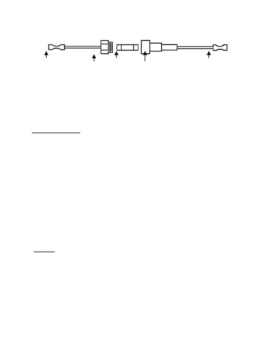
1. Fuse Holder, Qty. 1 (ea)
NSN 5920-00-242-2706
2. Splice, Crimp Type, Qty. 2 (ea)
NSN 5940-00-478-0037,
3. Fuse, 3 Amp/250V AC, Time Delay, MDL-3, Qty. 1 (ea)
NSN 5920-01-028-5727
6.2.5 Repair Procedures:
a) Ensure generator set is shut down. Disconnect negative battery terminal.
b) Locate A1, terminal 8, wire # 106B (the A1 is mounted right-center on the back wall inside of the
generator set control cabinet.
c) From terminal 8, follow wire # 106B back six inches from terminal 8 (remove wire ties as
necessary.) Cut wire # 106B at point six inches from terminal 8. Leave the six inches of wire and
terminal attached to terminal 8.
d) Locate fuse holder (index 1 above.) Strip both wire ends; crimp a splice (index 2 above) on both
ends.
e) Strip exposed ends of wire # 106B; crimp one fuse holder lead splice to each end of wire # 106B.
Fuse holder should now be inserted in series with wire # 106B.
f) Install fuse (index 3 above) in fuse holder. Secure fuse holder and leads with wire ties as
necessary.
g) Reconnect negative battery terminal
h) Modification complete
6.2.6 Test:
a) Start and run generator set.
b) Verify correct voltage and frequency.
c) Shut down set
d) Repeat steps a and step b.
e) Load test generator
6-2
