
TB 11-6115-741-24
Install
here
6.2.7 Troubleshooting Guidelines
If the fuse blows perform the following tests:
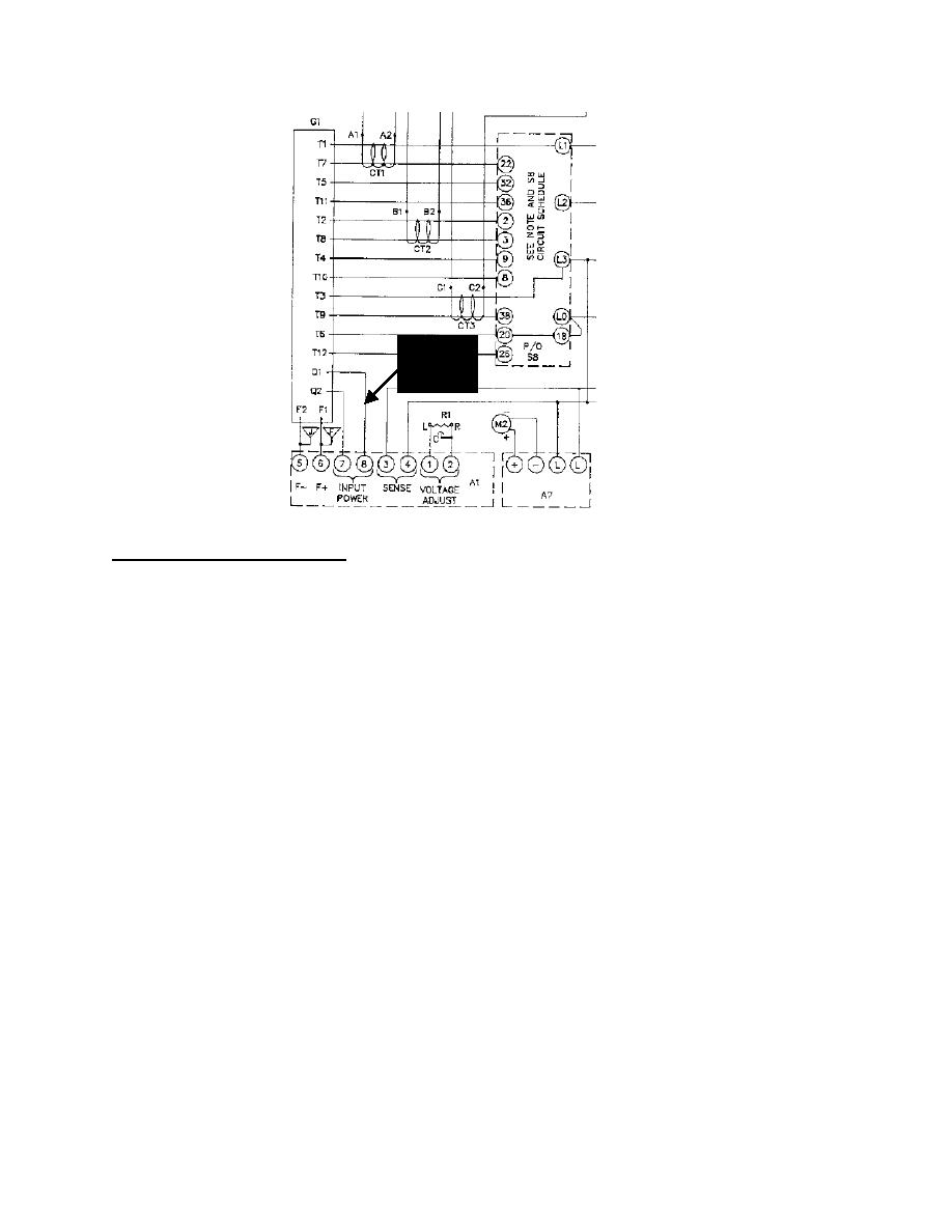
a) Disconnect wire # 106B from A1, terminal 8; disconnect wire # 107B from A1, terminal 7.
b) Connect a digital multimeter, set to "ohms," between A1 terminal 7 and A1 terminal 8.
Resistance value should be high. Low resistance indicates a defective bridge rectifier circuit.
Perform same test across A1 terminal 7 and A1 terminal 8 in "diode check" mode. Voltage drop
should be approximately 1-1.2 VDC. A zero (0) VDC reading indicates a defective bridge
rectifier circuit. If the resistance reading is low or the voltage reading is zero (0) the A1 must be
replaced.
c) With wire #'s 106B and 107B still disconnected, connect digital multimeter, set to "ohms,"
between wire # 106B and wire # 107B.
d) Check the "Quad" winding for proper resistance (Re: TM 9-6115-641-24, Figure 4-10.7, steps h
& i and TM 9-6115-642-24, Figure 4-10.7, steps h & i) Reading should be 0.9 1.2 ohms for the
MEP-802/803 and 1.2-1.6 ohms for the MEP 812/813. Verify resistance value does not drop
during test. If reading is out of tolerance the stator must be replaced
e) With "Quad" circuit still disconnected, test engine. If engine takes an excessive amount of time
to start or and/or an excessive amount of time to develop rated speed, troubleshoot the engine fuel
system. Verify that fuel system is free of contaminants. Verify condition of fuel filters. Verify
correct operation of electric fuel pumps. Verify combustion on all cylinders. Verify correct
installation and adjustment of injection pumps. Verify correct operation of injector nozzles.
Repair or replace components as necessary.
f) Retest engine and verify correct operation
g) Verify correct readings on A1 and "Quad" winding.
h) Reconnect wire # 106B to A1 terminal 8; reconnect wire # 107B to A1 terminal 7.
i) Install new fuse
j) Test generator set
6-3
