TM 9-6150-228-13&P
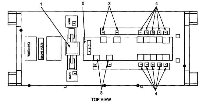
Figure 2-1. Power Distribution Panel Controls, Indicators, and Connectors.
2.1.5
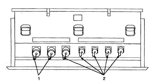
Connectors. 1 00-Amp (J3 through J6). Each 8-pin connector (1, Figure 2-2) is connected to, and controlled
by, a dedicated 100-amp circuit breaker. Together, they provide connection points for four 100-amp cables.
2.1.6
Connectors. 60-Amp (J7 through J16). Each 5-pin connector (2) is connected to, and controlled by a dedicated
60-amp circuit breaker. Together, they provide connection points for ten 60-amp cables.
Figure 2-2. 100-Amp/60 Amp Connectors.
2-2