TM 9-6150-226-13
Table 1-2.
DISE AND PDISE CABLES (Cont.)
Cable
Cable
Connector
Cable
No. of
No. of
Length
Weight
Diameter
Diameter
Cable
Amp
Pins/
Phase
f t .
l b .
Name
Rating
Sockets
Hires
(m)
(kg)
Extension
20
3
1
Branch
20
3
1
(1-drop)
Branch
20
3
1
(2-drop)
Branch
20
3
1
(3-drop)
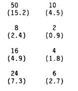
1.2
(31)
1.2
(31)
1.2
(31)
1.2
(31)
0.4
( l o )
0.4
( l o )
0.4
( l o )
0.4
( l o )
* These cables may be connected to the 40-amp or 60-amp, 5-pin, 3-phase connectors.
Table 1-3.
APPROXIMATE* VOLTAGE LOSSES AT RATED CURRENT
Rated Amperage/No. of Pins
200-amp/8-pin cables
100-amp/8-pin cables
60-amp/5-pin cables
40-amp/5-pin cables
60-amp/4-pin cables
20-amp/3-pin cables
1 V
0.4 V
0.5 V
0.3 V
0.5 V
1.1 V
Cable Length in Feet (Meters)
1.6 V
0.7 V
0.9 V
0.6 V
0.9 V
1.8 V
3.2 V
1.4 V
1.6 V
1.1 V
1.7 V
3.6 V
100
(30.5)
6.4 V
2.8 V
3.5 V
2.3 V
3.4 V
7.2 V
200
(61)
12.8 V
5.6 V
6.4 V
4.4 V
6.8 V
14.4 V
300
(91.4)
19.2 V
8.4 V
10.5 V
6.9 V
10.2 V
21.6 V
1-14.
EQUIPMENT CONFIGURATION
a.
Single-Phase System,
e l e c t r i c a l d i s t r i b u t i o n s y s t e m
with the following provisions:
* Actual voltage loss varies with actual current flow and conductor temperature.
The M60 and M60 A/P 60-amp, single-phase
(Fig. 1-6) can be used as a stand-alone system
1-19


