
TM 9-6115-729-24
0041
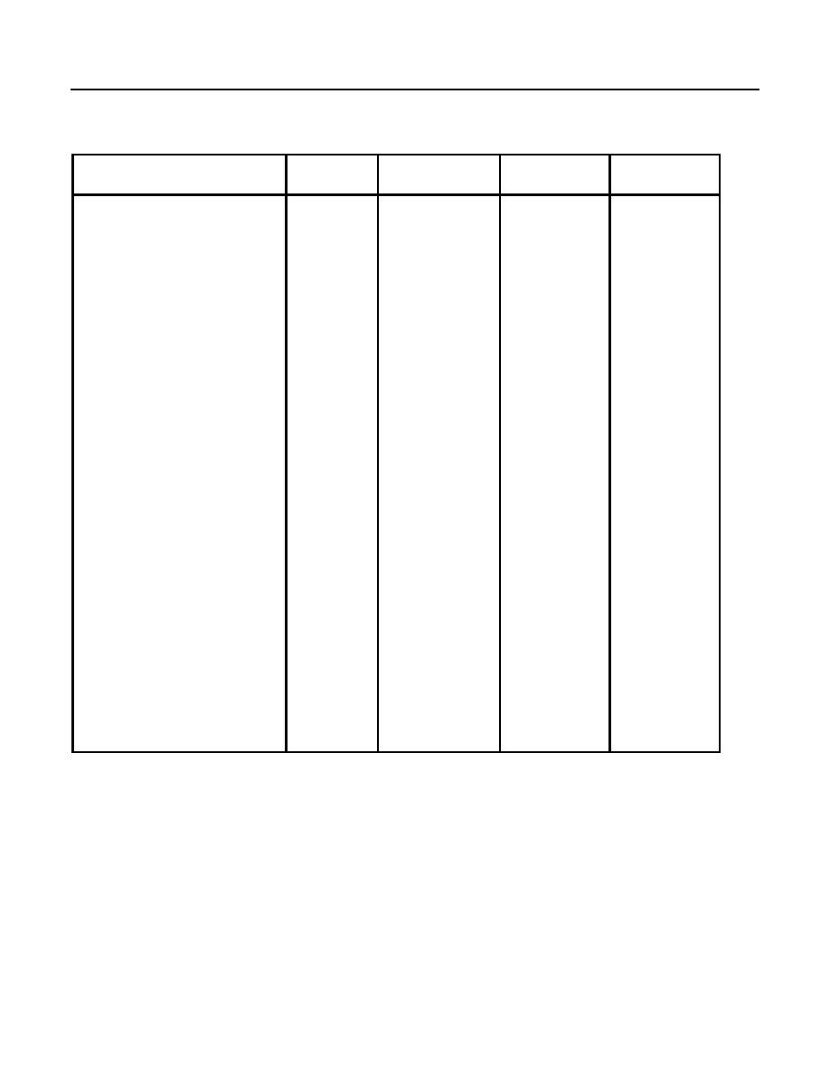
FIGURE 2
DISASSEMBLY
ASSEMBLY
RELATED
NAME
ITEM
STEPS
STEPS
STEPS
AC Transformer Box (ATB) A5
45
1, 2, and 14
16
1, 2, and 20
10
Alarm Reset (AR)
73
1, 2, and 20
10
Auxiliary Fuel Pump Relay
72
(AFPR)
Bus Transformer Box (BTB) A6
19
1, 2, and 7
23
1, 2, and 20
10
Cool Down Relay (CDR)
71
Dead Bus Relay, High Voltage
79
1, 2, and 21
9
Sensing (DBHI)
Dead Bus Relay, Low Voltage
78
1, 2, and 21
9
Sensing (DBLO)
Digital Voltage Regulator (DVR)
98
1, 2, and 26
4
A3
1, 2, and 20
10
Relay Field Flash (KFF)
75
1, 2, and 20
10
Generator Fault Relay (GFR)
74
Ground Fault Circuit Interrupter
42
1, 2, and 13
17
(GFCI)
Adjustment
Load Sharing Module (LSM) A4
28
1, 2, and 9
21
1 thru 4
Main Contactor Relay (KR)
70
1, 2, and 20
10
Overload/Short Circuit Module
24
1, 2, and 8
22
Paralleling Relay (PAR)
81
1, 2, and 22
8
Resistor Assembly A7
112
1, 2, and 28
2
REMOVAL
1. Ensure generator set is fully stopped, ENGINE CONTROL switch is set to OFF/RESET, Battery Disconnect
Switch is set to OFF, and DEAD CRANK SWITCH is OFF before proceeding.
2. Tag and disconnect harness connector P30 from Control Box connector J30.
3. Tag and disconnect harness connector P31 from Control Box connector J31.
4. Tag and disconnect ECM to EMCP harness connector ENG-P37 from Control Box connector J37.
5. Remove ground wire (Figure 1, Item 1), washer (Figure 1, Item 2) and locknut (Figure 1, Item 3) from back of
control box terminal (Figure 1, Item 4).
