
TM 9-6115-729-24
0014
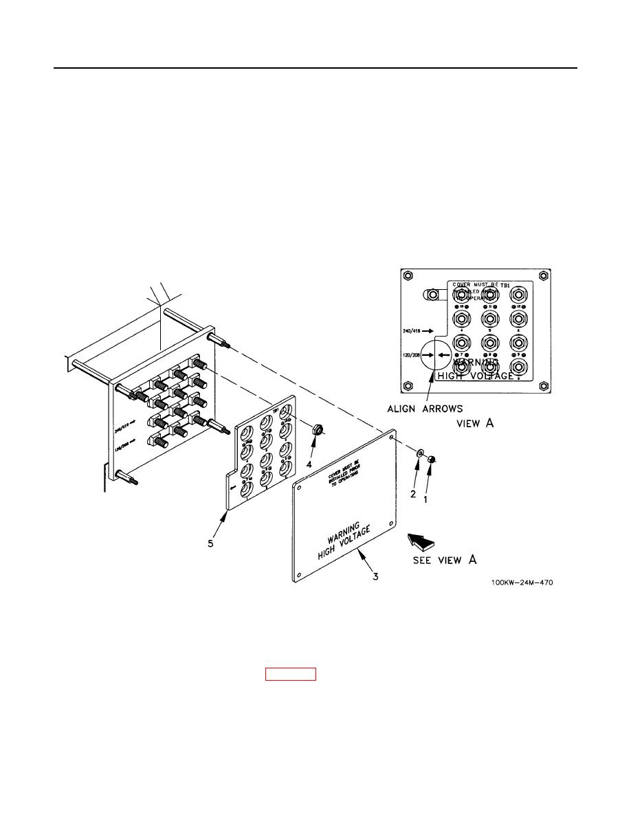
OUTPUT VOLTAGE SETTING - Continued
3. Remove four nuts (Figure 1, Item 1), washers (Figure 1, Item 2), and clear protective panel (Figure 1, Item 3)
from reconnection board.
4. Remove 12 nuts (Figure 1, Item 4) and reconnection board (Figure 1, Item 5).
5. Align arrow on reconnection board (Figure 1, Item 5) with arrow on base corresponding to desired generator
output voltage(s).
6. Install reconnection board (Figure 1, Item 5) and secure with 12 nuts (Figure 1, Item 4).
7. Install clear protective panel (Figure 1, Item 3) and secure with four washers (Figure 1, Item 2) and nuts
(Figure 1, Item 1).
8. Close right rear doors.
9. Reprogram DVR and GSC as required per WP 0085.
END OF WORK PACKAGE
0014-3/4 blank
