
TM 9-6115-729-24
0003
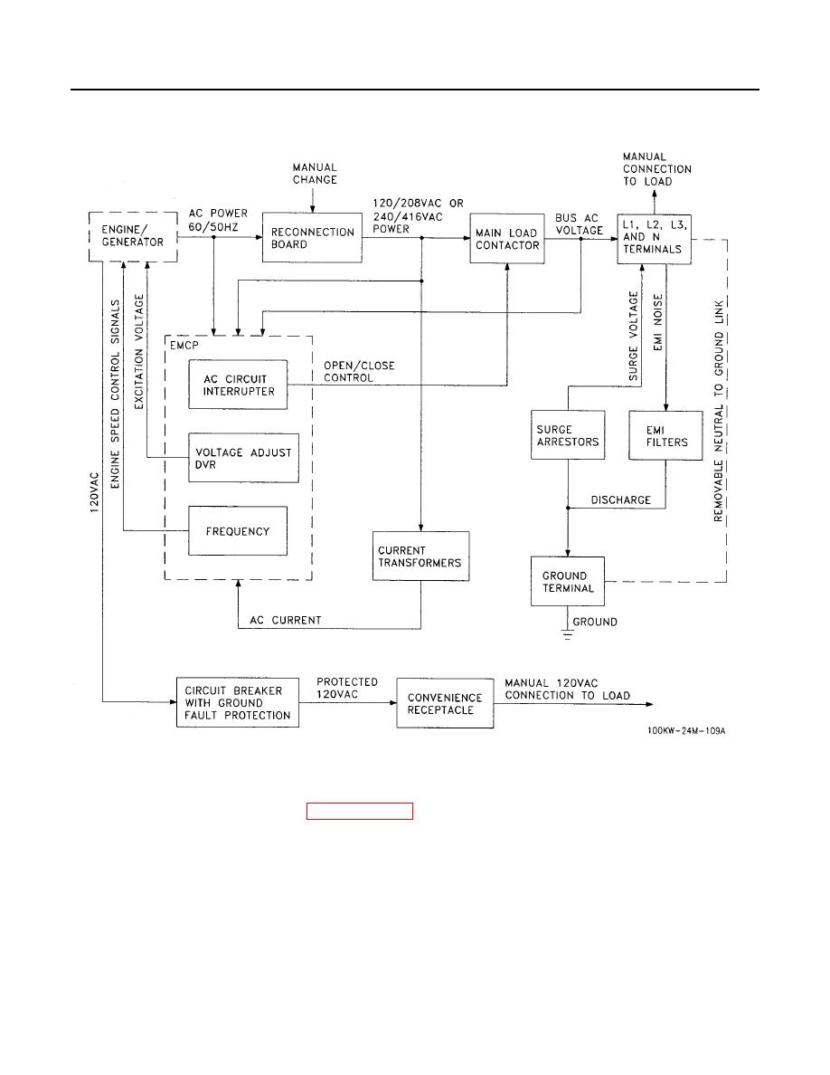
AC POWER OUTPUT - Continued
DC POWER DISTRIBUTION (FIGURE FO-1, SHEETS 2 AND 3)
The DC battery system (Figure 8) provides 24 Vdc for engine starting and TQG control circuits. The two 12 Vdc
batteries are charged by the engine alternator. The DC AMMETER on the EMCP indicates alternator charging
rate. Charge rate is shown from -25 to +50 A. Normal operating indication depends on the state of charge in the
batteries. A low charge, such as exists immediately after engine starting, will cause a high reading. The battery
system includes a manually operated Battery Disconnect Switch to isolate the batteries from the engine. The
Battery Disconnect Switch can be used to remove the DC power from the TQG. The batteries connect
directly to the 24 Vdc NATO slave receptacle.
