ARMY TM 9-6115-670-14&P
4-138
REPLACE
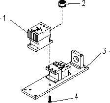
a. Refer to Figure FO-1 (SICPS/WIN-T) or F0-7 (JTACS) and tag and disconnect electrical leads from
terminals T1, T2, and T3 of main AC contactor (1) by loosening three screws.
b. Remove diode (number to be determined) from Terminals A1 and A2.
c. Reinstall diode (number to be determined) to Terminals A1 and A2 on main AC contactor, observing
the same polarity.
d. Remove main AC contactor (1) from contactor mounting plate (3) by removing two screws (4) and
two nut and captive washer assemblies (2).
e. Secure main AC contactor (1) to contactor mounting plate (3) by securing with two screws (4) and
two nuts and captive washer assemblies (2).
f. Refer to Figure FO-1 (SICPS/WIN-T) or F0-7 (JTACS) and connect electrical leads to terminals T1,
T2, and T3 of main AC contactor (1) and secure by tightening three screws.
Figure 4-41. Main AC Contactor (Sheet 2)
WARNING
Ensure that APU DC power supply is disconnected.
Failure to observe this warning could result in severe
injury or DEATH to personnel.
WARNING
Ensure that the APU is turned off and completely de-
energized before opening generator housing. Failure to
observe this warning could result in severe injury or
DEATH to personnel.
NOTE
Observe polarity of the diode.


