ARMY TM 9-6115-670-14&P
4-132
m. Inside generator housing, at bottom of terminal board (6), install two nuts with captive washers (14)
on two countersunk hex socket screws (17).
n. Install four terminal posts (8) and secure with four washers and four lock washers (19 and 7).
o. Inside generator housing, install electrical leads (9) to terminal posts (8) and secure with four flat
washers (10), lock washers (11), and nuts (12). Remove tags.
p. Install two jumper bars (20) on terminal posts.
q. Outside generator housing, install terminal leads to appropriate terminal posts (8) and secure four
flat washers (22), lock washers (23), and nuts (24).
r. Install four separators (3) and secure with four bolts (5) and star washers (4).
s. Install protective cover (25) and secure with four lock washers (2) and bolts (1).
t. Install generator housing top cover (16) and secure with four screws (JTACS), or slotted hex-head
bolts (SICPS and WIN-T), flat and lock washers (15).
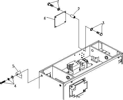
Figure 4-39. Electrical Output Terminal Board
NOTE
Refer to FO-1 or FO-7 for installation of jumper bars for low
voltage (120 VAC) and/or high voltage (240 VAC) power
connections.