ARMY TM 9-6115-670-14&P
4-70
e. Disconnect fuel return line at vehicle entrance fitting and cap fuel line to generator set with a fuel
tight plug. (Refer to System TM for location of vehicle fuel return lines.)
f. Disconnect J7(6) from P7(7) (Figure 4-17) and install jumper switch to P7(7) engine wiring harness.
(Ensure switch is off prior to connecting to wiring harness.)
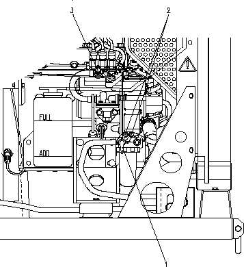
g. Open fuel valve (1, Figure 4-14) on fuel filter.
h. Open two bleed Screws (2, Figure 4-14) on fuel filter.
i. Turn MASTER SWITCH to ON position.
j. Turn Jumper Switch to ON position. When a solid stream of fuel flows from the fuel filter bleed
screws close the bleed screws and turn OFF the Jumper Switch.
k. Open Fuel injection Pump Bleed Screw (3, Figure 4-14).
l. Turn Jumper Switch to ON position. When a solid stream of fuel flows from the Fuel Injection Pump
Bleed Screw, close the Fuel Injection Pump Bleed Screw and turn the Jumper Switch to the OFF
position.
m. Turn MASTER SWITCH to OFF position.
n. Disconnect Jumper Switch from P7 and reconnect P7 to J7.
o. Reconnect fuel line to vehicle.
Figure 4-16. Fuel System