ARMY TM 9-6115-645-24
AIR FORCE TO 35C2-3-444-12
MARINE CORPS TM 09244A/09245A-24/2
a.
Place key (32, FIGURE 4-17) on rotor assembly (23) and install drive hub (31) over key (32) and onto main rotor
assembly (23) with set screw (30).
b.
Install rotating rectifier, paragraph 4-20.2.
c.
Install main bearing, paragraph 4-19.2.
CAUTION
Special care must be taken Installing rotor assembly, winding damage could resuit if rotor
Is allowed to hit main stator.
d.
Attach a suitable rotor lifting device to drive hub (31) and overhead hoist as shown in FIGURE 4-18.
e.
Carefully install rotor assembly (23) and attached components into main stator and generator housing (33).
f.
Install generator end bell, paragraph 4-19.2 and remove rotor lifting device.
g.
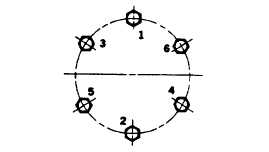
Install fan (29) on drive hub (31) with Belleville washers (28) mounted in direction shown in FIGURE 4-19, and
bolts (27). Torque bolts (27) to 60 ft-lbs (81 Nm) in sequence shown in FIGURE 4-20.
BELLEVILLE WASHERS
MUST BE MOUNTED IN THIS DIRECTION
FIGURE 4-19 Belleville Washer Mounting
FIGURE 4-20. Bolt Torque Sequence
NOTE
Make sure all disc mounting holes at the inner and outer diameter are properly aligned.
h.
Install drive discs (26, FIGURE 4-17) on drive hub (31) with washers (25) and bolts (24). Torque bolts (24) to 28
ft-lbs (38 Nm), refer to FIGURE 4-20 for bolt torque sequence.
i.
Install generator assembly in generator set, paragraph 4-17.2.
4-24.
GENERATOR MAIN STATOR AND HOUSING.
4-24.1. Testing.
a.
Shut down generator set. Allow generator to cool to ambient temperature.
b.
Open battery access door and disconnect negative battery cable.
c.
Remove protective cover and moveable terminal board from voltage reconnection terminal board, paragraph 2-
95.2.
d.
Disconnect two electrical connectors from bottom of control box assembly.
e.
Tag and disconnect wires 107C and 109J from terminals 1 and 2 of power potential transformer (37, FIGURE 4-
5).
Change 2 4-41