ARMY TM 9-6115-645-24
AIR FORCE TO 35C2-3-444-12
MARINE CORPS TM 09244A/09245A-24/2
d.
Remove generator end bell cover plates, paragraph 4-19.1, step h.
e.
Tag and disconnect main rotor leads (2 places) from rotating rectifier by removing nuts (1, FIGURE 4-16).
NOTE
It will be necessary to bar (turn) engine in order to position a specific area of the rotating
rectifier at one of the end bell access holes. Turn engine using center bolt on harmonic
balancer, refer to TM 9-2815-256-24.
f.
Set multimeter for ohms and connect between disconnected main rotor leads. Multimeter reading should be as
shown in TABLE 4-3.
g.
Reading other than in TABLE 4-3, indicates shorted or open windings and main rotor must be replaced.
h.
Connect multimeter between each main rotor lead and end bell in turn.
i.
Multimeter reading of less than infinity indicates defective ground insulation and main rotor must be replaced.
j.
Connect main rotor leads to rotating rectifier with nuts (1, FIGURE 4-16).
k.
Install generator end bell cover plates, paragraph 4-19.2, step h.
I.
Install generator set housing rear panel, paragraph 2-18.4
m.
Connect negative battery cable and close battery access door.
4-23.2. Removal.
a.
Shut down generator set.
b.
Remove generator assembly from generator set, paragraph 4-17.1.
c.
Remove bolts (24, FIGURE 4-17), washers (25), and drive disc (26) from drive hub (31).
d.
Remove bolts (27), Belleville washers (28), and fan (29) from drive hub (31).
e.
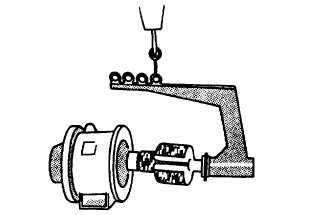
Attach a suitable rotor lifting device to drive hub (31) and overhead hoist as shown in FIGURE 4-18.
FIGURE 4-18. Rotor Assembly Lifting Device (Typical)
f.
Remove generator end bell, paragraph 4-19.1.
CAUTION
Special care should be taken when removing rotor assembly, winding damage
could result If rotor Is allowed to hit main stator.
g.
Carefully remove rotor assembly (23, FIGURE 4-17) and attached components from main stator and generator
housing (33).
h.
Remove main bearing, paragraph 4-19.1.
i.
Remove rotating rectifier, paragraph 4-20.1.
j.
Remove set screw (30), drive hub (31), and key (32) from rotor assembly (23).
4-23.3. Installation.
4-40 Change 2


