ARMY TM 9-115-644-24
AIR FORCE TO 35C2-3-446-12
MARINE CORPS TM 09249A/09246A-24/2
PROCEDURES:
NOTES:
1.
1. Dimensions shown are in inches.
2. Refer to TM 9-6115-644-24P for materials
2.
required.
3.
4.
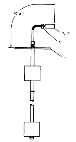
Strip 0.125 inch of insulation from end of each
switch (1) lead.
Crimp pin (2) on end of each lead.
lnsert pins into housing (3) with lead A in
position 1, lead Bin position 2, lead C in position
3, and lead D in position 4.
Mark “P12” on strap (4) and install in position
shown.
FIGURE D-25. Switch Assembly, Fuel Level (P/N: 88-22548)
D-25

