ARMY TM 9-6115-641-24
AIR FORCE TO 35C2-3-456-12
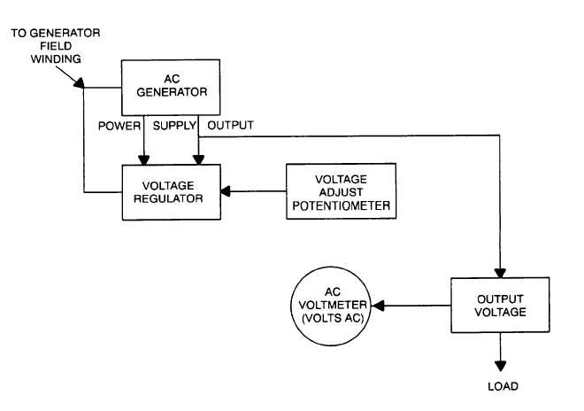
Figure 1-11. Voltage Regulation System
1-13-5. DEAD CRANK Switch (5) . The DEAD CRANK switch is located in the engine compartment on the left side. For
maintenance purposes the switch allows the engine to be cranked without starting.
1-13-6. Engine (6). The generator is powered by a two cylinder, four cycle, fuel injected, naturally–aspirated, liquid–
cooled diesel engine which occupies the front half of the generator set. The engine is also equipped with a fuel filter/water
separator, oil filter, and an air cleaner assembly. Protection devices automatically stop the engine during conditions of high
coolant temperature, low oil pressure, no fuel, and overvoltage.
1-13-7. Batteries (7). Two batteries are required, one on each side of the generator set. The batteries are electrolyte
serviceable, lead acid, 12 volt type, connected in series. After starting, the generator set is capable of operating with batter-
ies removed. A fuse and a diode, located behind the control panel assembly, protects the generator set if the batteries
are incorrectly connected.
1-13-8. Water Pump (8). The water pump is located in the engine compartment on the front of the engine. The pump
circulates the engine coolant through the engine block and the radiator.
1-13-9. Fuel Transfer Pump (9).The fuel transfer pump is located in the engine compartment on the front left side. The
pump is electrically operated and transfers fuel from the fuel tank to the engine through the fuel filter/water separator.
1-24


