ARMY TM 9-6115-639-13
AIR FORCE TO 35C2-3-386-51
MARINE CORPS TM 10155A-13/1
4-54. GOVERNOR ACTUATOR MAINTENANCE - cont.
3.
Open the control box panel to gain access to the
governor control module.
4.
Connect a multimeter between control module
terminals A and B.
5.
Start the generator set (paragraph 2-8) and run in
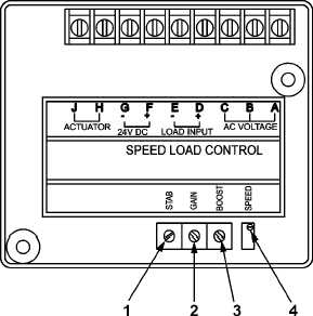
no load condition. Adjust control module SPEED
pot (4, Figure 4-50) to obtain a PMA frequency
of 254 Hz (3050 RPM) or a voltage of 178 +/- 2
volts AC. Clockwise rotation of the SPEED pot
increases frequency and voltage. Counter-
clockwise rotation decreases frequency and
voltage.
CAUTION
DO NOT loosen or adjust governor actuator
(2, Figure 4-51) magnet. The position of the
magnet is factory set.
Figure 4-50. Governor Control Module
6.
With engine running, check the gap between lever plate (19, Figure 4-51) and governor actuator magnet.
Gap shall be 5/16 inch. Adjust gap by loosening locknut (23) and screwing linkage rod (22) in or out of
ball joint (3). Check gap and tighten locknut (23).
7.
Turn the STABILITY pot (1, Figure 4-50) and
GAIN pot to the full counterclockwise position.
8.
Rotate control module STABILITY pot (1, Figure 4-50) clockwise until engine becomes unstable, then
counterclockwise until it stabilizes, and then a little further counterclockwise.
9.
Rotate control module GAIN pot (2) clock clockwise until engine becomes unstable, then
counterclockwise until it stabilizes, and then a little further counterclockwise.
10. Close load contactor and apply full rated load. Adjust control module BOOST pot (3) to obtain a PMA
frequency of 288 Hz (3450 RPM) or a voltage of 193 +/-2 volts AC. Clockwise rotation of the BOOST
pot decreases frequency and voltage. Counterclockwise rotation increases frequency and voltage.
4-135
Change 1