
1-15. INSTRUMENT PANEL. (See figure 1-4. )
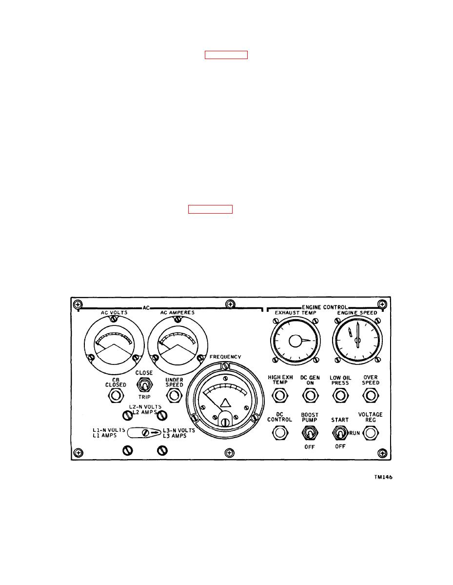
1-16. The instrument panel, housed in the top of the control console, simulates the
aircraft controls. It contains manually-actuated switches to operate the APU, and
gages and lights to indicate conditions of the APU during operation. All indicator lights
and instruments are visible when the instrument panel cover is lifted. The panel is
divided into two groups of controls; engine control and ac generator control. The
engine control group contains the pyrometer (exhaust temperature indicator), tachom-
eter indicator (engine speed indicator), HIGH EXH TEMP lamp, DC GEN ON lamp,
LOW OIL PRESS lamp, OVERSPEED lamp, BOOST PUMP switch, DC CONTROL
circuit breaker, VOLTAGE REG circuit breaker, and the engine START-RUN-OFF
quency meter, CB CLOSED lamp, GEN UNDERSPEED lamp, CLOSE-TRIP switch,
and the VOLTS-AMPS phase selector switch.
1-17. THERMOCOUPLE. (See figure 1-3. )
1-18. The thermocouple is stowed on the left side of the engine support frame. When
in use, the thermocouple is installed on the top side of the APU exhaust outlet. The
thermocouple probe projects into the exhaust stream and senses exhaust gas tempera-
ture at the alumelchromel junction. A small voltage is generated and converted to an
indication on the exhaust temperature indicator during engine operation.
Figure 1-4. Console Instrument Panel
1-5
