TM 5-6115-631-14&P
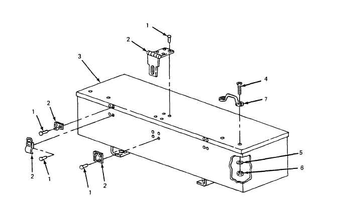
Figure 5-4. Accessory Box Repair.
b. Footmans Loop Replacement.
(1) Remove two screws (4, figure 5-4), two flat washers (5), and two self-locking nuts (6)
securing footmans loop (7) to accessory box lid.
(2) Position new footmans loop (7) on accessory box (3) and install two screws (4) two
washers (5), and two self-locking nuts (6).
5.6.
Marking. (See figure 5-5.) The power plant four-digit registration number, preceded by the
prefix “VC” and the words “U.S. ARMY, ” is marked in three places on the trailer. Marking is done in
accordance with MIL-STD-642. On the fender, over each wheel, “T.P. 50 PSI” is marked in 1.00 ±
.12 inch high characters in accordance with MIL-STD-130. On the switch box, “GEN 1”, “GEN 2“ and
“OFF” are marked on the cover at their respective switch lever positions, and “E1” and “E2” are marked
next to their respective ground terminal studs. Figure 5-5 shows the approximate location of markings
on the power plant. If required, touch-up painting of the base color shall be done in accordance with
MIL-T-704, Type F, color Green, No. 383 of MIL-C-46168.
5-8